Philips 32PF5320A Quick Use Guide - Page 3
Nputs, Omponent, Efinition - manual
 |
View all Philips 32PF5320A manuals
Add to My Manuals
Save this manual to your list of manuals |
Page 3 highlights
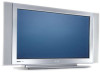
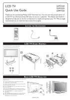
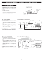
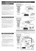
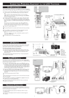
CONNECTING PERIPHERAL EQUIPMENT TO THE LCD TELEVISION AV INPUTS AV The audio/video input jacks on the bottom panel of the TV are for direct picture and sound connections between the TV and a VCR (or similar device) that has audio/video output jacks. 1 Using an RCA type Video Cable, connect one end of the cable to the Video (yellow) Out jack on the VCR or accessory device and the other end to the AV Video In jack on the bottom of the TV. 2 Using an RCA type Audio Left and Right Cable, connect one end to the left and right Audio Out L & R jacks (red & white) on the 4 VCR or accessory device and the other ends to the AV Audio In L & R jacks on the bottom of the TV. 3 Turn the VCR or accessory device and the TV On. 4 Press the AV button on the remote control to show the Source List menu on the TV screen. 5 5 Press the œ button repeatedly until AV is highlighted, then press the π button to enter the selected Mode. 6 With the VCR (or accessory device) ON and a prerecorded tape (CD, DVD, etc.) inserted, press the PLAY button to view the tape on the television. TUNE TO AV1 CHANNEL 1 VIDEO IN (YELLOW) 5 AUDIO IN (RED/WHITE) VCR (or accessory device) (EQUIPPED WITH VIDEO AND AUDIO OUTPUT JACKS) 2 6 3 Jack Panel Bottom of TV COMPONENT VIDEO INPUTS (CVI) Component Video inputs provide the highest possible color and picture resolution in the playback of digital signal source material, such as with DVD players. 1 Connect the Component (Y, Pb, Pr) Video OUT jacks from the DVD player (or similar device) to the CVI-1 VIDEO Input (Y green, Pb blue, Pr red) jacks on the bottom of the TV. 2 Connect the red and white AUDIO CABLES to the Audio (left and right) output jacks on the rear of the accessory device to the CVI-1 Audio In L & R jacks on the bottom of the TV. 3 Turn the TV and the DVD player (or digital accessory device) ON. 4 Press the AV button on the remote control to show the Source List menu on the TV screen. 5 Press the œ button repeatedly until CVI-1 is highlighted, then press the π button to enter the selected Mode. 6 Insert a DVD disc into the DVD player and press the PLAY button on the DVD Player. HD (HIGH DEFINITION) INPUTS If you are using a High Definition receiver that can transmit high definition programming, the TV can except those signals through the HD Inputs located on the bottom of the TV. 1 For Digital Connection, connect the HDMI connector of the HD Receiver (or similar device) to the HDMI Input jacks on the bottom of the TV. OR For Analog Connection, use Component Video cables to connect the Component (Y, Pb, Pr) Video Out jacks of the HD Receiver (or similar device) to the VGA adapter (supplied with the TV). Connect the other end of the adapter to the VGA Input jacks (CVI-2) on the bottom of the TV. 2 Connect the red and white audio cable to RCA type Audio Cables. Connect the audio adapter to the PC Audio In L & R jacks on the bottom of the TV. 3 Turn the TV and the HD Receiver ON. 4 Press the AV button on the remote control to show the Source List menu on the TV screen. 5 Press the œ button repeatedly until HDMI or CVI-2 (SD/HD) is highlighted, then press the π button to enter the selected Mode. CVI 2 4 5 Jack Panel Bottom of TV 1 COMPONENT VIDEO CABLES (Green, Blue, Red) 5 AUDIO CABLES (RED/WHITE) ACCESSORY DEVICE EQUIPPED WITH COMPONENT VIDEO OUTPUTS. 6 3 HELPFUL HINT The description for the component video connectors may differ depending on the DVD player or accessory digital source equipment used (for example, Y, Pb, Pr; Y, B-Y, R-Y; Y, Cr, Cb). Refer to your DVD player or digital accessory owner's manual for definitions and connection details. HDMI 3 1 4 5 5 Digital Connection 2 Analog Connection COMPONENT VIDEO CABLES Rear of HD Receiver (Illustration is for reference (Green, Blue, Red) only. Your HD Receiver's jack AUDIO panel may be CABLES labeled differently. HDMI CABLE HD RECEIVER EQUIPPED WITH 4 COMPONENT VIDEO OUTPUTS. 3 Coxial Cable Lead-in from Cable Outlet, Cable Converter Box, or VHF/ UHF Antenna Coaxial cable Lead-in from Satellite Dish or Antenna
-
 1
1 -
 2
2 -
 3
3 -
 4
4
 |
 |