Pioneer 1140HD Owner's Manual - Page 73
Computer compatibility chart, G-LINK™ connection
 |
UPC - 012562829593
View all Pioneer 1140HD manuals
Add to My Manuals
Save this manual to your list of manuals |
Page 73 highlights
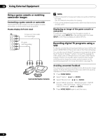
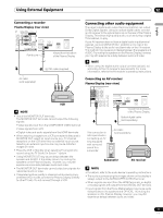
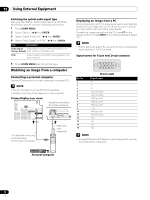
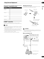
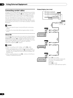
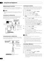
Using External Equipment 12 English Computer compatibility chart Resolution 720 × 400 640 × 480 800 × 600 1024 × 768 1360 x 768 Frequency 70 Hz 60 Hz 72 Hz 75 Hz 56 Hz 60 Hz 72 Hz 75 Hz 60 Hz 70 Hz 75 Hz 60 Hz G-LINK™ connection To record with a VCR through the TV Guide On Screen™ system, connect the VCR to the panel using the G-LINK cable. NOTE • In order to use a VCR with the TV Guide On Screen™ system, confirm the factors listed below. See "TV Guide On Screen™ System Setup" on page 32. • The G-LINK cable's wand must be positioned so that its light emitting section faces the VCR's remote control sensor. • The VCR is in Standby when selecting TV programs to record using the TV Guide On Screen™ system. • Avoid the cable loops when making the connection. Attaching the ferrite core To help prevent noise, attach the supplied ferrite core to the connector end of the G-LINK cable as shown. Ferrite core G-LINK cable Pull the cable slightly to take up any slack A. A As close as possible CAUTION • Regarding the G-LINK cable, attach the supplied ferrite core. If you do not do this, this Plasma Display will not conform to mandatory FCC standards. When connecting the VCR Plasma Display (rear view) Ferrite core Viewed from the bottom of the Plasma Display AV cable (sold separately) G-LINK cable (supplied) G-LINK cable's wand Point to the remote VCR control sensor 73 En
-
 1
1 -
2
-
3
-
4
-
5
-
6
-
7
-
8
-
9
-
10
-
11
-
12
-
13
-
14
-
15
-
16
-
17
-
18
-
19
-
20
-
21
-
22
-
23
-
24
-
25
-
26
-
27
-
28
-
29
-
30
-
31
-
32
-
33
-
34
-
35
-
36
-
37
-
38
-
39
-
40
-
41
-
42
-
43
-
44
-
45
-
46
-
47
-
48
-
49
-
50
-
51
-
52
-
53
-
54
-
55
-
56
-
57
-
58
-
59
-
60
-
61
-
62
-
63
-
64
-
65
-
66
-
67
-
 68
68 -
 69
69 -
 70
70 -
 71
71 -
 72
72 -
 73
73 -
 74
74 -
 75
75 -
 76
76 -
 77
77 -
 78
78 -
79
-
80
-
81
-
82
-
83
-
84
-
85
-
86
-
87
-
88
-
89
-
90
-
91
-
92
-
93
-
94
-
95
-
96
-
97
-
98
-
99
-
100
-
101
-
102
-
103
-
104
-
105
-
106
-
107
-
108
-
109
-
110
-
111
-
112
-
113
-
114
-
115
-
116
-
117
-
118
-
119
-
120
 |
 |
