Pioneer DEH-6400BT Owner's Manual - Page 13
Switching the dimmer setting, Using an AUX source, Turning the clock display on, or off, Connections - wiring
 |
View all Pioneer DEH-6400BT manuals
Add to My Manuals
Save this manual to your list of manuals |
Page 13 highlights
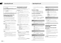
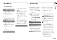
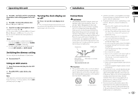
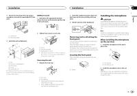
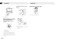
Operating this unit 4 Press M.C. and hold until the customizing illumination color setting appears in the display. 5 Press M.C. to select the primary color. R (red)-G (green)-B (blue) 6 Turn M.C. to adjust the brightness level. Adjustment range: 0 to 60 # You cannot select a level below 10 for all three of R (red), G (green), and B (blue) at the same time. # You can also perform the same operation on other colors. Notes ! You cannot create a custom illumination color when SCAN or a set of colors (WARM, AMBIENT, or CALM) is selected. ! You can create custom illumination colors for both KEY COLOR and DISP COLOR. Turning the clock display on or off % Press to turn the clock display on or off. # The clock display disappears temporarily when you perform other operations, but the clock display appears again after 25 seconds. Switching the dimmer setting You can adjust the brightness of illumination. % Press and hold . Using an AUX source 1 Insert the stereo mini plug into the AUX input jack. 2 Press SRC/OFF to select AUX as the source. Note AUX cannot be selected unless the auxiliary setting is turned on. For more details, refer to AUX (auxiliary input) on page 11. Installation Section 02 03 Connections WARNING ! Use speakers over 50 W (output value) and between 4 W to 8 W (impedance value). Do not use 1 W to 3 W speakers for this unit. ! The black cable is ground. When installing this unit or power amp (sold separately), make sure to connect the ground wire first. Ensure that the ground wire is properly connected to metal parts of the car's body. The ground wire of the power amp and the one of this unit or any other device must be connected to the car separately with different screws. If the screw for the ground wire loosens or falls out, it could result in fire, generation of smoke or malfunction. Ground wire POWER AMP Other devices Metal parts of car's body (Another electronic device in the car) Important ! When installing this unit in a vehicle without an ACC (accessory) position on the ignition switch, failure to connect the red cable to the terminal that detects operation of the ignition key may result in battery drain. F O OF N STAR T ACC position No ACC position ! Use this unit with a 12-volt battery and negative grounding only. Failure to do so may result in a fire or malfunction. ! To prevent a short-circuit, overheating or malfunction, be sure to follow the directions below. - Disconnect the negative terminal of the battery before installation. - Secure the wiring with cable clamps or adhesive tape. Wrap adhesive tape around wiring that comes into contact with metal parts to protect the wiring. - Place all cables away from moving parts, such as the shift lever and seat rails. - Place all cables away from hot places, such as near the heater outlet. - Do not connect the yellow cable to the battery by passing it through the hole to the engine compartment. - Cover any disconnected cable connectors with insulating tape. - Do not shorten any cables. - Never cut the insulation of the power cable of this unit in order to share the power with other devices. The current capacity of the cable is limited. - Use a fuse of the rating prescribed. - Never wire the negative speaker cable directly to ground. - Never band together negative cables of multiple speakers. ! When this unit is on, control signals are sent through the blue/white cable. Connect this cable to the system remote control of an external power amp or the vehicle's auto-antenna relay control terminal (max. 300 mA 12 V DC). If the vehicle is equipped with a glass antenna, connect it to the antenna booster power supply terminal. ! Never connect the blue/white cable to the power terminal of an external power amp. Also, never connect it to the power terminal of the auto antenna. Doing so may result in battery drain or a malfunction. En 13 English
-
 1
1 -
2
-
3
-
4
-
5
-
6
-
7
-
 8
8 -
 9
9 -
 10
10 -
 11
11 -
 12
12 -
 13
13 -
 14
14 -
 15
15 -
 16
16 -
 17
17 -
 18
18 -
19
-
20
-
21
-
22
-
23
-
24
-
25
-
26
-
27
-
28
-
29
-
30
-
31
-
32
-
33
-
34
-
35
-
36
-
37
-
38
-
39
-
40
-
41
-
42
-
43
-
44
-
45
-
46
-
47
-
48
-
49
-
50
-
51
-
52
-
53
-
54
-
55
-
56
-
57
-
58
-
59
-
60
-
61
-
62
-
63
-
64
-
65
-
66
-
67
-
68
-
69
-
70
-
71
-
72
 |
 |