Pioneer DJM-800 Owner's Manual - Page 20
Midi Messages, Synchronizing Audio Signals, To External Sequencer, Or, Using Djm-800 Information - trim
 |
UPC - 012562796604
View all Pioneer DJM-800 manuals
Add to My Manuals
Save this manual to your list of manuals |
Page 20 highlights
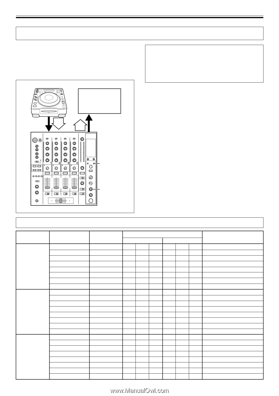
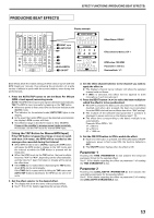
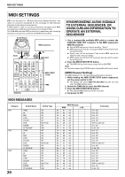
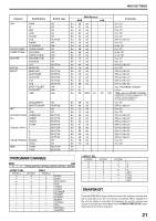
MIDI SETTINGS MIDI SETTINGS MIDI is an acronym for "Musical Instrument Digital Interface" and refers to a protocol developed for the exchange of data between electronic instruments and computers. A MIDI cable is used to connect components equipped with MIDI connectors to enable the transmission and receipt of data. The DJM-800 uses the MIDI protocol for transmitting and receiving data about component operation and BPM (timing clock). DJ CD Player MIDI sequencer OUT Audio IN BPM =120 BPM =120 IN MIDI OUT DJM-800 MIDI START /STOP TIME SYNCHRONIZING AUDIO SIGNALS TO EXTERNAL SEQUENCER, OR USING DJM-800 INFORMATION TO OPERATE AN EXTERNAL SEQUENCER 1. Use a commercially available MIDI cable to connect the DJM-800's MIDI OUT connector to the MIDI sequencer's MIDI IN connector. ¶ Set the MIDI sequencer's synch mode to "Slave". ¶ MIDI sequencers that do not support MIDI timing clock cannot be synchronized. ¶ Synch may not be achieved if the track's BPM cannot be detected and measured stably. ¶ BPM values set with the TAP mode can also be used to output the timing clock. 2. Press the MIDI START/STOP button. ¶ The MIDI timing clock output range is 40 to 250 BPM. Note: ¶ Accurate measuring of BPM may be impossible with some tracks. [MIDI Channel Setting] The MIDI channel (1 to 16) can be set and stored in memory. 1. While holding the MIDI START/STOP button depressed, set the power switch to ON. ¶ The display will show [MIDI CH SETTING] and the unit will enter the MIDI setting mode. 2. Rotate the TIME dial to select the MIDI channel. 3. Press the MIDI START/STOP button. ¶ The selected MIDI channel will be recorded. 4. Set power to OFF. MIDI MESSAGES Category CH1 CH2 CH3 20 Switch Name TRIM HI MID LOW COLOR CUE FADER CF ASSIGN TRIM HI MID LOW COLOR CUE FADER CF ASSIGN TRIM HI MID LOW COLOR CUE FADER CF ASSIGN Switch Type VR VR VR VR VR BUTTON VR SW VR VR VR VR VR BUTTON VR SW VR VR VR VR VR BUTTON VR SW MIDI Message MSB LSB Bn 01 dd Bn 02 dd Bn 03 dd Bn 04 dd Bn 05 dd Bn 46 dd Bn 11 dd Bn 41 dd Bn 06 dd Bn 07 dd Bn 08 dd Bn 09 dd Bn 0A dd Bn 47 dd Bn 12 dd Bn 42 dd Bn 0C dd Bn 0E dd Bn 0F dd Bn 15 dd Bn 16 dd Bn 48 dd Bn 13 dd Bn 43 dd Comments 0 to 127 0 to 127 0 to 127 0 to 127 0 to 127 OFF=0, ON=127 0 to 127 0, 64, 127 0 to 127 0 to 127 0 to 127 0 to 127 0 to 127 OFF=0, ON=127 0 to 127 0, 64, 127 0 to 127 0 to 127 0 to 127 0 to 127 0 to 127 OFF=0, ON=127 0 to 127 0, 64, 127
-
 1
1 -
2
-
3
-
4
-
5
-
6
-
7
-
8
-
9
-
10
-
11
-
12
-
13
-
14
-
 15
15 -
 16
16 -
 17
17 -
 18
18 -
 19
19 -
 20
20 -
 21
21 -
 22
22 -
 23
23 -
 24
24
 |
 |