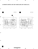
Pioneer GM-7150M Service Manual - Page 20
Pcb Connection Diagram
 |
UPC - 012562725604
View all Pioneer GM-7150M manuals
Add to My Manuals
Save this manual to your list of manuals |
Page 20 highlights
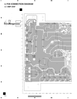
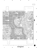
1 2 3 4 4. PCB CONNECTION DIAGRAM 4.1 AMP UNIT A NOTE FOR PCB DIAGRAMS 1.The parts mounted on this PCB A AMP UNIT include all necessary parts for several destination. For further information for respective destinations, be sure to check with the schematic dia- gram. 2.Viewpoint of PCB diagrams Connector Capacitor SIDE A B SIDE B P.C.Board Chip Part SPEAKER OUTPUT SPEAKER OUTPUT C POWER SUPPLY D E F A 20 1 3 2 1 3 2 1 3 2 1 3 2 1 3 2 1 3 2 1 GM-7100M/XU/EW 2 3 4
-
 1
1 -
2
-
3
-
4
-
5
-
6
-
7
-
8
-
9
-
10
-
11
-
12
-
13
-
14
-
 15
15 -
 16
16 -
 17
17 -
 18
18 -
 19
19 -
 20
20 -
 21
21 -
 22
22 -
 23
23 -
 24
24 -
 25
25 -
26
-
27
-
28
-
29
-
30
-
31
-
32
 |
 |
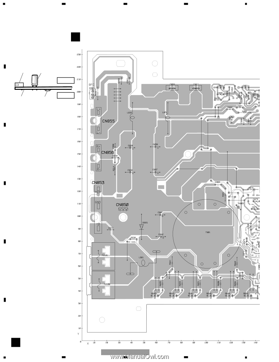
4. PCB CONNECTION DIAGRAM
4.1 AMP UNIT
Capacitor
Connector
P.C.Board
Chip Part
A
A
AMP UNIT
SIDE B
SIDE A
NOTE FOR PCB DIAGRAMS
1.The parts mounted on this PCB
include all necessary parts for
several destination.
For further information for
respective destinations, be sure
to check with the schematic dia-
gram.
2.Viewpoint of PCB diagrams
3
2
1
3
2
1
3
2
1
3
2
1
3
2
1
3
2
1
SPEAKER
OUTPUT
SPEAKER
OUTPUT
POWER
SUPPLY
20
1
2
3
4
1
2
3
4
F
E
D
C
B
A
GM-7100M/XU/EW