Pioneer GM-7150M Service Manual - Page 30
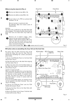
Caution when re-assembling the Amp Unit and the Heat Sink, Removing the Amp Unit Fig. 3
 |
UPC - 012562725604
View all Pioneer GM-7150M manuals
Add to My Manuals
Save this manual to your list of manuals |
Page 30 highlights
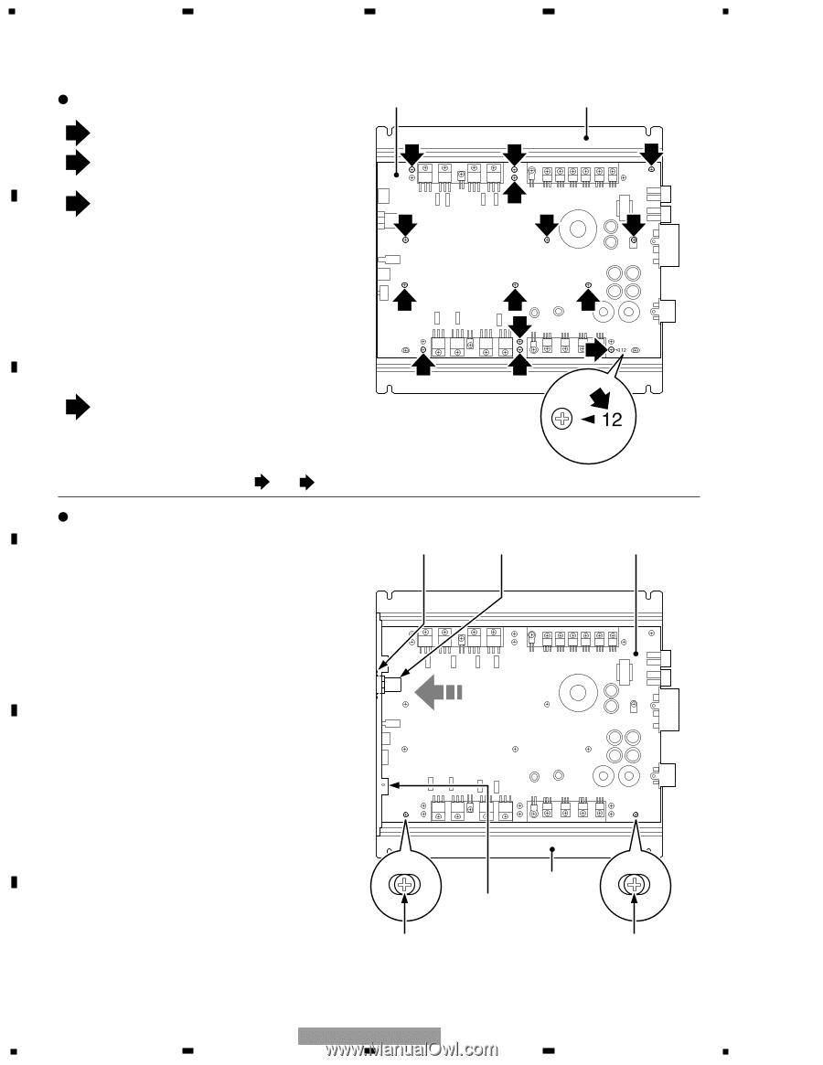
1 2 3 4 Removing the Amp Unit (Fig. 3) A 1 Remove six black screws (M3 x 10). 2 Remove six white screws (M3 x 12). Amp Unit 1 A Screw holes in the PCB are printed with numbers 1 to 12. 2 Remove screws in numerical order. Re-assembly takes the reverse order of B disassembly. Caution) The Amp Unit is adhered on the Heat Sink with silicon grease. This means forcibly removing the Amp Unit from the Heat Sink may break the PCB. 2 1 Remove all of twelve screws. Then, 3 remove the two black screws (M3 x 5). Tighten screws whose length is M3 x 8 or more into the two screw holes so as to C raise the Amp Unit above the Heat Sink. Then, remove the Amp Unit. (Since screw threads differ, 1 and 2 screws cannot be used.) Heat Sink 1 1 3 2 2 2 2 3 1 1 A Fig. 3 Caution when re-assembling the Amp Unit and the Heat Sink Be aware that the RCA Terminal may break unless the Amp Unit and the Heat Sink are assem-bled following the correct procedures given below. 1) Secure the RCA-side Panel on the Heat Sink D with screws. (Fig. 2) 2) Place the Amp Unit on the Heat Sink aligning with two studs. (Fig. 4) 3) Move the Amp Unit until the RCA Holder on the Amp Unit comes in contact with the inside of the Panel. (Fig. 4) Caution in steps 2) and 3) When you place the Amp Unit on the Heat Sink, you will find no positioning marks to determine the direction of two panels. To position them E correctly, the Amp Unit needs to be moved to the place where it comes in contact with the RCA-side panel. If you do not position them, an excessive force can be applied to the RCA Terminal. This may result in breakage. 4) Secure the RCA-side Panel and the RCA Holder with screws. (Fig. 2) 5) Secure the Amp Unit on the Heat Sink with screws. (Fig. 3) F 6) Secure the Panel for the Power Terminal side in place with screws. (Fig. 2) RCA Holder RCA Terminal (CN111) Amp Unit Move the Amp Unit Stud Heat Sink Panel for the RCA side Stud Fig. 4 30 GM-7100M/XU/EW 1 2 3 4
-
 1
1 -
2
-
3
-
4
-
5
-
6
-
7
-
8
-
9
-
10
-
11
-
12
-
13
-
14
-
15
-
16
-
17
-
18
-
19
-
20
-
21
-
22
-
23
-
24
-
 25
25 -
 26
26 -
 27
27 -
 28
28 -
 29
29 -
 30
30 -
 31
31 -
 32
32
 |
 |