Polaroid FLM-2632 Service Manual - Page 23
Rear Cabinet Cover LCD Panel and Front Bezel - 26
 |
UPC - 826219004925
View all Polaroid FLM-2632 manuals
Add to My Manuals
Save this manual to your list of manuals |
Page 23 highlights
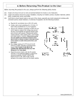
Rear Cabinet Cover LCD Panel and Front Bezel Note: Before disassembly of any part the TV, make sure the power is OFF, and the power cord is removed from the wall outlet. Allow time for power within all system boards to discharge before you begin disassembly. Never insert any objects into the vent holes in the TV case. Note: OEM LCD panels were used in production. The following LCD panel disassembly/removal instructions may not apply to all models. Ensure LCD panel is completely detached from the bezel before removing so the bezel is not damaged. (1) Remove screws (PIC1) in the sequence of 1, A. (2) Remove screws (PIC1) in sequence of 2, 3, 4, B, C, D (3) Remove screws which fasten rear cabinet to front frame (PIC1) in the following sequence: AÆBÆCÆDÆEÆF then 1Æ2Æ3Æ4Æ5 (4) Remove rear cabinet cover. Only the rear cabinet cover will come off. *NOTE: Pictured is a 26" model. 32" and 37" models will have some different rear cabinet cover screw quantities and locations. 23 www.polaroid.com
-
 1
1 -
2
-
3
-
4
-
5
-
6
-
7
-
8
-
9
-
10
-
11
-
12
-
13
-
14
-
15
-
16
-
17
-
 18
18 -
 19
19 -
 20
20 -
 21
21 -
 22
22 -
 23
23 -
 24
24 -
 25
25 -
 26
26 -
 27
27 -
 28
28 -
29
-
30
-
31
-
32
-
33
-
34
-
35
-
36
-
37
-
38
-
39
-
40
-
41
-
42
-
43
-
44
-
45
-
46
-
47
-
48
-
49
-
50
-
51
-
52
 |
 |
