Poulan 20112x92e0 User Manual - Page 7
Assemble Upper Handle, Assemble Upstop Bracket, Assemble Wheels, Assemble Discharge Guard
 |
View all Poulan 20112x92e0 manuals
Add to My Manuals
Save this manual to your list of manuals |
Page 7 highlights
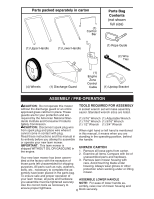
1. Position lower handle on housing so cut-off flat is forward as shown. 2. Align holes in handle with holes in housing as shown and assemble 3/816 x 3/4 hex bolts, flat washers, and locknuts. Tighten securely. 3. Repeat for opposite side of mower. Flat washers Locknuts Hex bolts Lower handle Cut-off flat forward ASSEMBLE WHEELS Cutting height is determined by assembling the wheels in one of four possible positions on the mower housing. All wheels must be in the same height position for even cutting. 1. For each wheel, assemble shoulder bolt and spacer as shown. 2. Assemble 1-1/4" diameter washers (rear wheels only) and 3/8-16 locknuts on inside of mower housing and tighten securely. 1-1/4" diameter Washer (Rear wheels only) Mower housing Shoulder bolt Spacer ASSEMBLE UPPER HANDLE 1. Position upper handle over lower handle with small hole for mounting up-stop bracket to right side and assemble 1/4-20 x 1-1/2 hex bolts and 1/4-20 locknuts. Tighten securely. ASSEMBLE UPSTOP BRACKET 2. Position upstop bracket on the right inside of upper handle as shown. 3. Install the hex washer head screw into the hole in up-stop bracket and upper handle. Tighten securely. AS VIEWED FROM FRONT OF MOWER Up-stop bracket 3/8-16 Wheel Locknut ASSEMBLE DISCHARGE GUARD 1. Place discharge guard on top of lawn mower discharge opening. 2. Install two (2) 1/4-20 x 3/4 hex bolts through housing and discharge guard. 3. Install two (2) 3/4" diameter washers and two (2) 1/4-20 locknuts. Tighten securely. Locknuts Washers Hex washer head screw Hex bolts Lock nuts Discharge guard Hex bolts 7
-
 1
1 -
 2
2 -
 3
3 -
 4
4 -
 5
5 -
 6
6 -
 7
7 -
 8
8 -
 9
9 -
 10
10 -
 11
11 -
 12
12 -
13
-
14
-
15
-
16
-
17
-
18
 |
 |
