Poulan C42C User Manual - Page 10
Use Hardware -GROUP E & F
 |
View all Poulan C42C manuals
Add to My Manuals
Save this manual to your list of manuals |
Page 10 highlights
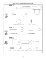
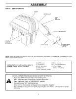
7 CHUTE LATCH ASSEMBLY (See Fig. 7) Use Hardware - - GROUP "E & F" 1. Assemble latch pin to upper chute, as shown. 2. Press weld nut into rubber latch and assemble rubber latch to lower chute, as shown. 3. Tighten all hardware securely. SCREW #10 x 1-1/8" WASHERS 3/16 x 3/4 x 16 Ga. SPLIT SPACER UPPER CHUTE ACORN NUT SCREW #10 x 5/8" RUBBER LATCH LOWER CHUTE WELD NUT 02102 WASHER 3/16 x 3/4 x 16 Ga. LOCK WASHER FIG. 7 9 UPPER CHUTE (See Fig. 9A & 9B) No hardware required 1. Lower mower deck to its lowest cutting position. 2. Assemble upper chute by inserting curved end into hole in back of cover. NOTE: Handle carefully so as not to damage dump bag indicator. 3. Push in and turn upper chute until it is in line with lower chute. 4. Align the bosses on lower chute with alignment slots on upper chute and slide together. 5. Secure with rubber latch by hooking hole in latch over latch pin. COVER UPPER CHUTE DUMP BAG INDICATOR HANDLE 02099 LOWER CHUTE 8 CONTAINER MOUNTING (See Fig. 8) No hardware required 1. Install one container to left side first with warning to outside of unit. Install other container to right side. NOTE: Right container should always overlap left container at center support. 2. Close cover and lock latch handle over center support tube. COVER LATCH HANDLE CONTAINER WARNING WARNING CONTAINER HANDLE csDWruaobcAjnkeoecRtdt otNooprewIdrNeaaatmeGramagnoedwdd.eUertsuieenrlioeonsraslytcioaonnr.etCaciohnmeecrmkisebnpadrgoepfdreerrqelyupielsanctelym. Reenpt lcaocnetawinheern. 02082 FIG. 8 CENTER SUPPORT TUBE CONTAINER WARNING FIG. 9A ALIGNMENT SLOT LATCH PIN 02098 RUBBER LATCH BOSSES FIG. 9B 10 LEVEL MOWER DECK Be sure deck is properly leveled for best mower performance. See your tractors owner's manual for instructions. 10
-
 1
1 -
2
-
3
-
4
-
 5
5 -
 6
6 -
 7
7 -
 8
8 -
 9
9 -
 10
10 -
 11
11 -
 12
12 -
 13
13 -
 14
14 -
 15
15
 |
 |
