Poulan C42C User Manual - Page 8
MOUNTING TO TRACTOR See Fig. 4, Use Hardware -GROUP C, CONTAINER ASSEMBLY See Fig. 5, No hardware
 |
View all Poulan C42C manuals
Add to My Manuals
Save this manual to your list of manuals |
Page 8 highlights
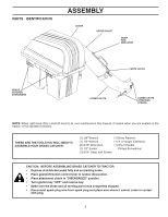
4 MOUNTING TO TRACTOR (See Fig. 4) Use Hardware - - GROUP "C" NOTE: For ease of assembly, you may wish to obtain the assistance of another person for mounting assembly to tractor. 1. Raise seat on tractor to allow assembly to be mounted. 2. With cover closed, lift assembly and place support post inside mounting bracket. Allow assembly to rest on lanced tabs of mounting bracket. 3. Line up holes in mounting bracket with holes in support post and insert bracket support pin.Secure with retainer spring. 4. Unlatch and open cover. 5. Install the three (3) tubing end caps onto container support. 6. Tap each end cap onto container support tubes to seat securely. BRACKET SUPPORT PIN COVER ASSEMBLY 5 CONTAINER ASSEMBLY (See Fig. 5) No hardware required 1. Place bottom half inside of top half, as shown. 2. Place one foot inside bottom half and lift top half to meet bottom half. 3. Press halves tightly together while lifting top to lock into place as shown. IMPORTANT: BEFORE LOCKING THE TABS, HOOKED EDGES ON BOTH HALVES MUSTOVERLAPTOFORMSEALASSHOWN IN INSET. 4. Repeat for other containers. CONTAINER BOTTOM HALF 02089 CONTAINER TOP HALF RETAINER SPRING CONTAINER TOP HALF 02096 02739 PRESS TOGETHER TO FORM SEAL WHILE LIFTING TOP HALF END CAP SUPPORT POST LANCED TABS MOUNTING BRACKET FIG. 4 CONTAINER BOTTOM HALF LOCKING TAB FIG. 5 ASSEMBLY CHECK: Squeeze sides of lower half of container and check that there is no gap between upper and lower halves. If a gap appears, unlock tabs to separate container halves and repeat instructions above. 02097 W DrneldnyoietsAlnyds.ouRrRteboepjNepplacelIatcrNcaetoetmGewwemenhaoterwcnoacennrratduacnkidneleeedtsrie.sorricodoraanmttiaoainng.eeCrdih.seUpcsrkoebpoaenglyfraeqreucomme 8
-
 1
1 -
2
-
 3
3 -
 4
4 -
 5
5 -
 6
6 -
 7
7 -
 8
8 -
 9
9 -
 10
10 -
 11
11 -
 12
12 -
 13
13 -
14
-
15
 |
 |
