ProForm 445i Treadmill English Manual - Page 9
Set the Console 78 on the Left and Right Uprights 9
 |
View all ProForm 445i Treadmill manuals
Add to My Manuals
Save this manual to your list of manuals |
Page 9 highlights
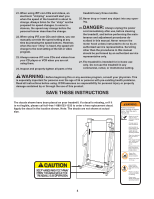
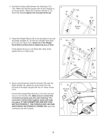
7. Set the Console (78) on the Left and Right Uprights (9, 7 10). Be careful not to pinch any wires. See drawing 6 on page 8. Make sure that the Upright Wire Harness (17) is not in the small cutout shown by the arrow. Using the included 90° screwdriver and a phillips screw- driver, attach the Console (78) to the Uprights (9, 10) and the Crossbar (88) with six 3/4" Screws (39). Start all six Screws before tightening any of them; be careful not to overtighten the Screws. 39 10 8. Lower the Uprights (9, 10) until the handrails are touching the floor. 8 See the lower drawing. Position the Uprights (9, 10) so that the treadmill Frame (12) is centered between the Uprights. Firmly tighten the four 2 3/4" Bolts (47). Then, raise the Uprights (9, 10) back to the vertical position. 78 88 39 39 9 9, 10 47 Handrail Top View 10 9. Remove the knob from the pin. Make sure that the collar and the spring are on the pin as shown. Insert the pin 9 into the Latch Housing (77), and tighten the knob back onto the pin. 9 12 Knob 77 Collar 9 Pin Spring 10. Make sure that all parts are properly tightened before you use the treadmill. Note: Extra hardware may be included. Keep the included allen wrench in a secure place. The allen wrench is used to adjust the walking belt (see page 24). To protect the floor or carpet, place a mat under the treadmill. 9
-
 1
1 -
2
-
3
-
 4
4 -
 5
5 -
 6
6 -
 7
7 -
 8
8 -
 9
9 -
 10
10 -
 11
11 -
 12
12 -
 13
13 -
 14
14 -
15
-
16
-
17
-
18
-
19
-
20
-
21
-
22
-
23
-
24
-
25
-
26
-
27
-
28
-
29
-
30
-
31
-
32
 |
 |
