ProForm 585 Ekg Elliptical User Manual - Page 9
INSTALLING THE RECEIVER FOR THE OPTIONAL CHEST PULSE SENSOR, Make sure that no wires, are pinched.
 |
View all ProForm 585 Ekg Elliptical manuals
Add to My Manuals
Save this manual to your list of manuals |
Page 9 highlights
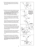
INSTALLING THE RECEIVER FOR THE OPTIONAL CHEST PULSE SENSOR If you purchase the optional chest pulse sensor (see page 21), follow the steps below to install the receiver and the jumper wire included with the chest pulse sensor. 1. Remove the four indicated screws from the back of the Console (23). Lift off the front of the Console. 1 23 Lift Here Short Screws Long Screws 2. Plug the jumper wire (A) into the indicated jack on the Console (23). Connect the other end of the jumper wire 2 to the wire on the receiver (B). Note: Any other wires included with the chest pulse sensor can be discarded. 23 Next, peel the paper off the adhesive pad on the back of the receiver (B). Orient the receiver as shown, and press it onto the Console (23) in the indicated location. See step 1 above. Reattach the front of the Console (23) with the four screws. Make sure that no wires are pinched. B Cylinder Jack A 9
-
 1
1 -
2
-
3
-
 4
4 -
 5
5 -
 6
6 -
 7
7 -
 8
8 -
 9
9 -
 10
10 -
 11
11 -
 12
12 -
 13
13 -
 14
14 -
15
-
16
-
17
-
18
-
19
-
20
-
21
-
22
-
23
-
24
-
25
-
26
-
27
-
28
 |
 |
