ProForm 660 Xt Uk Manual - Page 5
Carriage Bolts 34 and two M10 Nylon Locknuts
 |
View all ProForm 660 Xt manuals
Add to My Manuals
Save this manual to your list of manuals |
Page 5 highlights
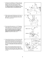
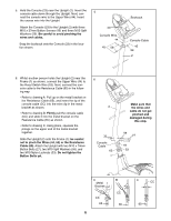
1. Identify the Front Stabiliser (10). Whilst another person lifts the front of the Frame (1), attach the Front Stabiliser to the Frame with two M10 x 75mm Carriage Bolts (34) and two M10 Nylon Locknuts (33). Make sure that the Front Stabiliser is turned so the Wheels (22) are not touching the floor. 1 22 22 10 2. Whilst another person lifts the back of the Frame (1) 2 slightly, attach the Rear Stabiliser (9) to the Frame with two M10 x 75mm Carriage Bolts (34) and two M10 Nylon Locknuts (33). 34 33 1 3. The Console (23) requires four 1.5 V "D" batteries; alkaline batteries are recommended. Press the tab on the battery cover, and lift off the battery cover. Insert four batteries into the battery compartment. Make sure that the batteries are oriented as shown by the diagram inside the battery compartment. Reattach the battery cover. 3 Battery Cover Batteries 1 33 33 9 34 Tab 23 4. Connect the wire harness on the Pulse Sensor (29) 4 to the indicated wire harness on the Console (23). Insert both wire harnesses into the opening in the bottom of the Console. Next, insert the metal tube on the Pulse Sensor into the opening in the bottom of the Console. Be careful not to pinch the wire har- nesses. Refer to the inset drawing. Align the holes in the bracket on the Console (23) with the holes in the metal tube on the Pulse Sensor (29). Tighten an M4 x 16mm Screw (52) through the bracket into the tube as shown. 23 23 52 Tube Tube Wire Harnesses 29 Bracket 29 5
-
 1
1 -
 2
2 -
 3
3 -
 4
4 -
 5
5 -
 6
6 -
 7
7 -
 8
8 -
 9
9 -
 10
10 -
 11
11 -
12
-
13
-
14
-
15
-
16
 |
 |
