ProForm 705 Zlt Treadmill Uk Manual - Page 12
If You Do Not Connect The Con
 |
View all ProForm 705 Zlt Treadmill manuals
Add to My Manuals
Save this manual to your list of manuals |
Page 12 highlights
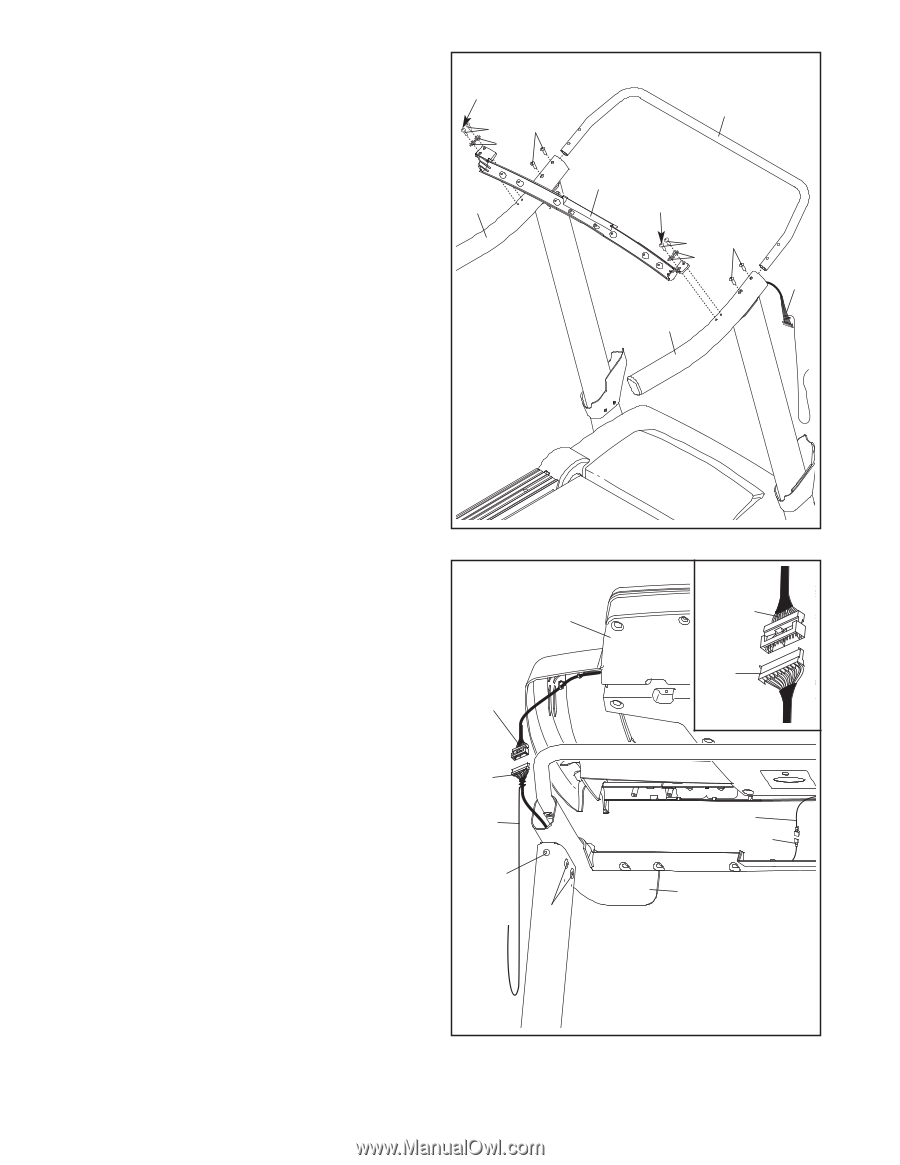
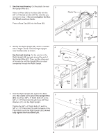
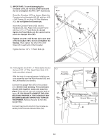
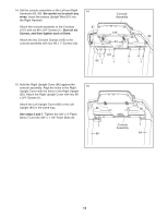
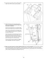
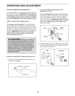
12. IMPORTANT: To avoid damaging the Crossbar (107), do not use power tools and 12 do not overtighten the #10 x 3/4" Screws (2). First 102 Orient the Crossbar (107) as shown. Attach the 29 Crossbar to the Handrails (82, 83) with four #10 12 x 3/4" Screws (2) and four #10 Star Washers (12); do not tighten the Screws yet. 107 82 Insert the Console Frame (102) into the Handrails (82, 83). Attach the Console Frame with four 1/4" x 1" Patch Bolts (9); do not tighten the Patch Bolts yet. Be careful not to pinch the Upright Wire (87). First 29 12 87 Tighten one #10 x 3/4" Screw (2) in each end 83 of the Crossbar (107); do not overtighten the Screws. Then, tighten the other #10 x 3/4" Screw (2) in each end of the Crossbar. Tighten the four 1/4" x 1" Patch Bolts (9). 13. Firmly tighten two 5/16" x 1" Patch Bolts (4) and the four 5/16" x 1" Flat Head Patch Bolts (14) (only one side is shown). With the help of a second person, hold the console assembly near the Right Handrail (83) and the Left Handrail (not shown). Connect the Upright Wire (87) to the console wire. See the inset drawing. The connectors should slide together easily and snap into place. If they do not, turn one connector and try again. IF YOU DO NOT CONNECT THE CONNECTORS PROPERLY, THE CONSOLE MAY BECOME DAMAGED WHEN YOU TURN ON THE POWER. Remove the wire tie from the Upright Wire. Connect the ground wire from the console assembly to the Console Ground Wire (52). 13 Console Assembly Console Wire 87 Wire Tie 4 14 Console Wire 87 Ground Wire 52 83 12
-
 1
1 -
2
-
3
-
4
-
5
-
6
-
 7
7 -
 8
8 -
 9
9 -
 10
10 -
 11
11 -
 12
12 -
 13
13 -
 14
14 -
 15
15 -
 16
16 -
 17
17 -
18
-
19
-
20
-
21
-
22
-
23
-
24
-
25
-
26
-
27
-
28
-
29
-
30
-
31
-
32
-
33
-
34
-
35
-
36
 |
 |