ProForm 705 Zlt Treadmill Uk Manual - Page 7
do not fully fold the Frame yet., Make sure that the power cord is unplugged., Repeat this step
 |
View all ProForm 705 Zlt Treadmill manuals
Add to My Manuals
Save this manual to your list of manuals |
Page 7 highlights
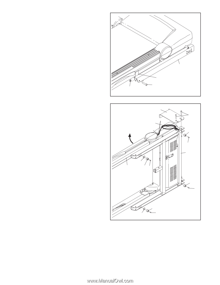
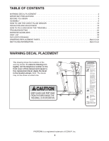
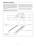
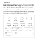
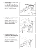
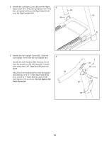
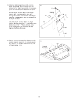
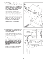
1. Make sure that the power cord is unplugged. 1 Remove the 3/8" Nut (10), the 3/8" x 2" Bolt (8), and the shipping bracket (A) from the Base (95). Repeat this step on the other side of the treadmill. The 3/8" Nuts (10) and the 3/8" x 2" Bolts (8) will be used in assembly steps 3 and 6. Discard the shipping brackets. A 8 10 2. With the help of a second person, carefully tip the treadmill onto its left side. Partially fold the 2 Frame (55) so that the treadmill is more stable; do not fully fold the Frame yet. Remove and discard the two indicated bolts (B) and the shipping bracket (C). Cut the shipping tie securing the Upright Wire (87) to the Base (95). Locate a plastic tie in the indicated hole in the Base, and use the tie to pull the Upright Wire out of the hole. Attach two Base Feet (90) to the Base (95) in the locations shown with two #8 x 1" Tek Screws (5) and two Base Foot Spacers (94). Then, attach the other two Base Feet (90) with two #8 x 1" Tek Screws (5). C Hole 87 94 55 90 5 90 94 5 95 B 90 5 95 90 5 7
-
 1
1 -
 2
2 -
 3
3 -
 4
4 -
 5
5 -
 6
6 -
 7
7 -
 8
8 -
 9
9 -
 10
10 -
 11
11 -
 12
12 -
13
-
14
-
15
-
16
-
17
-
18
-
19
-
20
-
21
-
22
-
23
-
24
-
25
-
26
-
27
-
28
-
29
-
30
-
31
-
32
-
33
-
34
-
35
-
36
 |
 |