ProForm 730 Owners Manual - Page 14
Model, PFTL17040
 |
View all ProForm 730 manuals
Add to My Manuals
Save this manual to your list of manuals |
Page 14 highlights
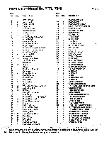
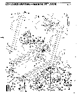
PART LIST Model No. PFTL17040 Key No. Qty. Description Key No. Qty. 1 4 2 1 3 1 4 8 5 4 6 1 7 1 8 1 9 1 10 1 11 1 12 1 13 1 14 1 15 3 16 1 17 4 18 10 19 17 20 1 21 1 22 20 23 1 24 1 25 1 26 4 27 28 1 29 2 30 2 31 1 32 6 33 2 34 5 35 1 ,36 1 -d- t 1 38 4 39 4 40 1 41 1 42 1 43,. 1 44 1 '45 2 46 2 47 2 48 2 49 1 50 1 3/8" x 2" Bolt Left Upright Safety Key/Clip Cage Nut Console Screw 70" Wire Harness 24" Cable Loom Console Pulse Earclip/Clothes Clip Strain Relief Front Left Endcap Front Roller/Pulley Right Upright Front Roller Adjustment Bolt Roller Adjustment Washer Front Right Endcap 3/8" x 3.5" Bolt Flat Washer Safety Cover Screw 12" Cable Loom Belt Guide Screw Choke Electronics Bracket Grommet Power Board Nut On/Off Switch Power Cord Wheel Bolt Front Wheel Controller Wheel Nut/Cushion Foot Nut Incline Leg Bolt 3/8" Nut Safety Cover Bracket Incline Leg Power Board r -O3-21 Power Board Bo t Power Board Spacer Frame Right Foot Rail Front Safety Cover Rear SafetyCover Walking Belt Cushion Foot Cover Small Nut Optic Switch Small Bolt Incline Optic Disk incline Motor Bracket 51 2 52 1 53 1 54 2 55 4 56 4 57 4 58 2 59 2 60 5 61 1 62 1 63 1 64 1 65 1 66 1 67 8 68 1 69 1 70 1 71 1 72 1 73 1 74 1 75 1 76 2 77 1 78 1 79 2 80 1 81 1 82 1 83 1 84 1 85 1 86 1 87 1 88 2 89 1 90 1 91 2 # 1 # 1 # 1 # 1 # 1 # 1 # 1 R794A Description Incline Motor Bolt Incline Motor Incline Motor Spacer Optic Switch Wire Harness Endcap Screw Cushion Foot Bolt 3/8" Jam Nut Cushion Foot 4" Cable Tie 8" Cable Tie Tie Block Tie Block Screw 3/16" Allen Wrench Wrench Clip Rear Roller Left Rear Endcap Platform Screw Walking Platform Left Foot Rail Motor Tension Bolt 20- " Wire Harness Motor Tension Nut Motor Mount Bracket Pulley/FlywheeVFan Motor Belt Motor Bolt Motor Motor Swivel Bolt Motor Nut Speed Optic Disk Optic Switch Bracket 14" Power Board-Controller Wire Cable Tie Wrap Right Rear Endcap Circuit Breaker Optic Switch Biacket Nut Power Cord B(acket Handrail Endcap Console Plate 7/32" Allen/Wrench Rear Roll& Adjustment Bolt 8" WhitpWire, Male/Female 14" Wtiffe-Wire, 2 Female 4" Black Wire, 2 Female 8" Black Wire, 2 Female 8" Green Ground Wire 8" Red Wire, Male/Female 8" Blue Wire, 2 Female Owner's Manual Note: -"-4," indicates a non-illustrated part. Specifications are subject to changewithout notice. See the 14 back cover for infonn4tion about ordering replacement parts.
-
 1
1 -
2
-
3
-
4
-
5
-
6
-
7
-
8
-
 9
9 -
 10
10 -
 11
11 -
 12
12 -
 13
13 -
 14
14 -
 15
15 -
 16
16
 |
 |
