ProForm 755 Ekg Bike Uk Manual - Page 6
mm Carriage Bolts 43 and two M10 Nylon
 |
View all ProForm 755 Ekg Bike manuals
Add to My Manuals
Save this manual to your list of manuals |
Page 6 highlights
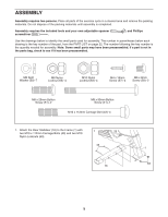
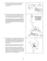
2. Orient the Front Stabiliser (15) as shown. Attach the Front Stabiliser to the Frame (1) with two M10 x 112mm Carriage Bolts (43) and two M10 Nylon Locknuts (63). 2 43 15 3. While another person holds the Upright (2) in the position shown, connect the Upper Wire Harness (42) to 3 the Lower Wire Harness (66). Gently pull the upper end of the Upper Wire Harness to remove any slack. Insert the Upright (2) into the Frame (1). Be careful to avoid pinching the Wire Harnesses (42, 66). Attach the Upright with two M8 x 25mm Button Screws (51), an M8 x 90mm Button Screw (41), and three M8 Split Washers (50). 1 63 Make sure that the wire harnesses do not get pinched and damaged during this step. 2 1 50 51 42 66 51 41 50 4. Slide the two slots in the Handlebar Bracket (13) onto the two indicated tabs on the Upright (2). Lift the bottom of the Handlebar Bracket away from the Upright, and insert the Handlebar (3) between the Handlebar Bracket and the Upright. Centre the Handlebar and rotate it to the desired position. Identify the Handlebar Handle (5), which has a longer threaded shaft than the Seat Handle (not shown). Insert the Handlebar Handle (5) into the Handlebar Bracket (13), and tighten the Handlebar Handle into the Upright (2). Note: The Handlebar Handle functions like a spanner. Turn the Handle clockwise, pull it away from the Upright, turn it counterclockwise, push it toward the Upright, and then turn it clockwise again. 4 3 Tabs 13 5 2 6
-
 1
1 -
 2
2 -
 3
3 -
 4
4 -
 5
5 -
 6
6 -
 7
7 -
 8
8 -
 9
9 -
 10
10 -
 11
11 -
 12
12 -
13
-
14
-
15
-
16
-
17
-
18
-
19
-
20
-
21
-
22
-
23
-
24
 |
 |
