ProForm 770s English Manual - Page 6
Assembly
 |
View all ProForm 770s manuals
Add to My Manuals
Save this manual to your list of manuals |
Page 6 highlights
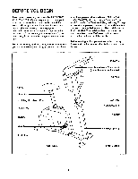
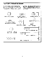
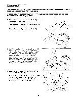
ASSEMBLY Place all parts of the PROFORM 770S in a cleared area and remove the packing materials. Do not dispose of the packing materials until assembly is completed. In addition to the included alien wrenches and two adjustable wrenches €*=:=D . , assembly requires a phillips screwdriver C 1 - 1. Refer to drawing 1A. Loosen the Lock Knob (38) on the right side of the Frame (1). Refer to drawing 1. Slide the Handlebar Frame (2) forward until it stops. Refer to drawing 1A. Tighten the Lock Knob (38) 1 2 1A 1 38 0 2. Identify the Left Pedal (52); there is an "L" on the Left Pedal for identification. Using an adjustable wrench, 2 tighten the Left Pedal counterclockwise into the left arm of the Crank (17). Tighten the Right Pedal (not shown) clockwise into the right arm of the Crank. Adjust the Pedal Strap (15) on the Left Pedal (52) to the desired position. Press the Pedal Strap onto the adjustment tab. Adjust the Pedal Strap on the Right Pedal (not shown) in the same manner. 0 15 Adjustment 52 Tab 3. Make sure that there is a Stabilizer Endcap (45) on each end of the Stabilizer (9). 3 Attach the Stabilizer (9) to the Frame (1) with two 3/8" x 2 3/4" Carriage Bolts (63) and two 3/8" Nylon Locknuts (56). Make sure that the Stabilizer is turned 1 so the dimples are in the indicated position. 56 17 I 56 45 Dimples 45 9 63 6
-
 1
1 -
 2
2 -
 3
3 -
 4
4 -
 5
5 -
 6
6 -
 7
7 -
 8
8 -
 9
9 -
 10
10 -
 11
11 -
 12
12 -
13
-
14
-
15
-
16
 |
 |
