ProForm 770s English Manual - Page 7
ProForm 770s Manual
 |
View all ProForm 770s manuals
Add to My Manuals
Save this manual to your list of manuals |
Page 7 highlights
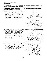
4. Refer to drawing 4A. The Console (58) requires two "AA" batteries (not included). Alkaline batteries are recommended. Press two batteries into the battery clip under the Console. Make sure that the negative (-) ends of the batteries are touching the springs. Refer to drawing 4. Insert the console wire through the Handlebar Post (4). Attach the Console (58) to the Handlebar Post with four Console Screws (12). Connect the console wire to the Reed Switch Wire (60) at the top of the Handlebar Frame (2). Insert the Handlebar Post (4) into the Handlebar Frame. Be careful to avoid pinching the wires. Attach the Handlebar Post with two 3/8" x 3 1/2" Screws (55), two M10 Flat Washers (57), and two 3/8" Nylon Locknuts (56). 5. Refer to drawing 5. Remove the four round stickers from the Handlebar Bracket (10) and the Handlebar Post (4). Attach the Handlebar Bracket to the Handlebar Post with two 1/4" x 1" Screws (54) and the two M12 OD Flat Washers (73). Make sure that the square hole is on the left side. Note: This step shows how to assemble the Resistance Dial (11) on the right side of the Handlebar Post (4). To assemble the Resistance Dial on the left side, reverse the orientation of the Resistance Bracket (10), 6" Carriage Bolt (16), M10 Star Washer (14), and Resistance Dial. Hold the lower end of the Left Handlebar (5) inside the Handlebar Bracket (10). Insert the 3/8" x 6" Carriage Bolt (16) into the Handlebar Bracket and through the Left Handlebar. Hold the Right Handlebar (6) inside the Handlebar Bracket. Insert the Carriage Bolt until the head of the Carriage Bolt is resting in the square hole in the Handlebar Bracket. Slide the M10 Star Washer (14) onto the Carriage Bolt. Tighten the Resistance Dial (11) onto the Carriage Bolt. Align the holes in the Handlebars (5, 6) with the hole in the Handlebar Post (4). Insert the Lock Pin (53) through the Handlebars and the Handlebar Post. Be careful not to damage the wire inside the Handlebar Post. 6. Insert the Seat Post (3) into the Frame (1). Align one of the holes in the Seat Post with the hole in the Frame. Insert the Seat Knob (37) into the Frame and the Seat Post, and tighten the Seat Knob into the Frame. Make sure to insert the Seat Knob through one of the holes in the Seat Post; do not insert the Seat Knob under the Seat Post. Attach the Seat (36) to the Seat Post (3) with four M8 Nylon Locknuts (46) and four 5/16" Flat Washers (26). (Note: The Nylon Locknuts and Flat Washers may be preattached to the bottom of the Seat.) 4 4A O "I® Batteries O 58 58 Oo Console Wire 12 4 55 60 Console Wire 2 5 4 54 73 10 16 OO 11 53 14 6 6 36 3 37 26 • 26 46 1 7
-
 1
1 -
 2
2 -
 3
3 -
 4
4 -
 5
5 -
 6
6 -
 7
7 -
 8
8 -
 9
9 -
 10
10 -
 11
11 -
 12
12 -
13
-
14
-
15
-
16
 |
 |
