ProForm 900 Elliptical Uk Manual - Page 10
mm Button Bolts 71 and two M8 Nylon
 |
View all ProForm 900 Elliptical manuals
Add to My Manuals
Save this manual to your list of manuals |
Page 10 highlights
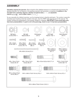
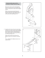
10. Identify the Right Handlebar (9), which is 10 marked with an "R" sticker. Insert the Right Handlebar into one of the Handlebar Legs (11) as shown. Attach the Right Handlebar (9) with two M8 x 42mm Button Bolts (71) and two M8 Nylon Locknuts (96). Make sure that the Nylon Locknuts are inside the hexagonal holes. Repeat this step for the Left Handlebar (not shown) and the other Handlebar Leg (not shown). 9 71 96 Hexagonal Holes 11 11. Orient an Inner Handlebar Cover (18) and an 11 Outer Handlebar Cover (19) around the Right Handlebar (9) as shown. Attach the Outer Handlebar Cover (19) with an M4 x 16mm Flange Screw (84). Then, attach the Inner Handlebar Cover (18) with two M4 x 16mm Self-tapping Screws (79). 79 9 18 84 Repeat this step for the Left Handlebar (not 19 shown). 10
-
 1
1 -
2
-
3
-
4
-
 5
5 -
 6
6 -
 7
7 -
 8
8 -
 9
9 -
 10
10 -
 11
11 -
 12
12 -
 13
13 -
 14
14 -
 15
15 -
16
-
17
-
18
-
19
-
20
-
21
-
22
-
23
-
24
-
25
-
26
-
27
-
28
 |
 |
