ProForm Crosswalk Zxt4 Treadmill English Manual - Page 12
If You Do Not Connect The Con
 |
View all ProForm Crosswalk Zxt4 Treadmill manuals
Add to My Manuals
Save this manual to your list of manuals |
Page 12 highlights
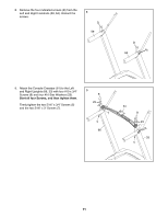
10. With the help of a second person, hold the console assembly near the Right Handrail (64). Connect the Upright Wire (63) to the console wire. See the inset drawing. The connectors should slide together easily and snap into place. If they do not, turn one connector and try again. IF YOU DO NOT CONNECT THE CONNECTORS PROPERLY, THE CONSOLE MAY BECOME DAMAGED WHEN YOU TURN ON THE POWER. Then, remove the wire tie from the Upright Wire. Connect the console ground wire to the ground wire on the Console Crossbar (61). 10 Console Assembly Console Wire 63 64 Ground Wires 61 Console Wire 63 11. Insert the wires into the Right Handrail (64) through the indicated hole as you set the con- 11 sole assembly on the Left and Right Uprights (66, 33). Make sure that no wires are pinched. Console Assembly See the inset drawing. When setting the console assembly onto the Uprights (66, 33), make sure that the indicated anges (only one is shown) on the Console Base (58) do not sit on top of the Uprights. They must be on the sides of the Uprights as shown. Attach the console assembly with ten #8 x 3/4" Screws (4). Start all ten Screws, and then tighten them; do not overtighten the Screws. Firmly tighten the six 3/8" x 3 1/4" Screws (2) on the lower ends of the Left and Right Uprights (66, 33) (only one side is shown). Wires Hole 64 4 4 33 Wires 4 4 4 66 2 12 58 66 Flange
-
 1
1 -
2
-
3
-
4
-
5
-
6
-
 7
7 -
 8
8 -
 9
9 -
 10
10 -
 11
11 -
 12
12 -
 13
13 -
 14
14 -
 15
15 -
 16
16 -
 17
17 -
18
-
19
-
20
-
21
-
22
-
23
-
24
-
25
-
26
-
27
-
28
 |
 |
