ProForm E35s Treadmill English Manual - Page 6
Assembly - the
 |
View all ProForm E35s Treadmill manuals
Add to My Manuals
Save this manual to your list of manuals |
Page 6 highlights
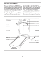
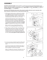
ASSEMBLY Assembly requires two people. Set the treadmill in a cleared area and remove the packing materials. Do not dispose of the packing materials until assembly is completed. Assembly requires the included allen wrench and your own 7/16" and 9/16" wrenches , rubber mallet , wire cutters , and Phillips screwdriver. Use the part chart attached in the center of this manual to identify small parts used in assembly. Each bag of hardware is labeled with the corresponding assembly step. 1. With the help of another person, carefully tip the treadmill onto its left side. Have the other person continue to hold the treadmill during steps 1 through 4. Note: Only half of the hardware in the bags for steps 1 to 3 will be used. The remaining hardware will be used at the end of step 4. Identify the Right Upright (58), which contains the Wire Harness (55). Insert the round tube on the Right Upright into the Base (117) as shown. If necessary, apply grease to the round tube and use a rubber mallet. Hold a Star Washer (113) between the indicated tab and the Base, and Finger tighten an Upright Bolt (66) through the tab into the Base. Make sure that the two indicated Walking Platform Screws (114) in the Walking Platform (100) are tight. 2. Attach a Base Leg (78) to the Base (117) with two Base Leg Bolts (77) and two Base Leg Nuts (70). Make sure that the Base Pad (75) is in the position shown. (Note: The Base Leg Nuts fit into square holes in the Base. If necessary, push or pull on the Right Upright [58] to align the holes.) Do not fully tighten the Base Leg Bolts yet. 1 66 Tab 113 117 2 77 66 75 78 77 70 117 55 58 58 100 114 3. See the inset drawing. Identify the right Front Wheel (62) by observing the direction that the Wheel Bracket (64) slants. Locate four 3/4" Screws (12) in hardware bag number 4. Attach the Wheel Bracket (64) on the right Front Wheel (62) to the Base (117) with the four Screws. 3 62 117 103 Attach a Thin Base Pad (103) and a Thick Base Pad (75) to the Base (117) with two 3/4" Screws (12) as shown. 64 12 62 Right Left 12 75 64 6
-
 1
1 -
 2
2 -
 3
3 -
 4
4 -
 5
5 -
 6
6 -
 7
7 -
 8
8 -
 9
9 -
 10
10 -
 11
11 -
 12
12 -
13
-
14
-
15
-
16
-
17
-
18
-
19
-
20
-
21
-
22
-
23
-
24
-
25
-
26
-
27
-
28
-
29
-
30
-
31
 |
 |
