ProForm E35s Treadmill English Manual - Page 7
Next, tighten the four Base Leg Bolts 77. Make sure
 |
View all ProForm E35s Treadmill manuals
Add to My Manuals
Save this manual to your list of manuals |
Page 7 highlights
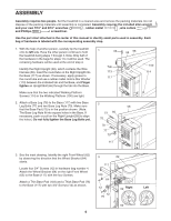
4. Locate the Belly Pan Wire Harness (124). Route the Belly Pan Wire Harness over the Base (117) as shown. Connect the Belly Pan Wire Harness to the Wire Harness (55). See the bottom inset drawing. The connectors should slide together easily and "snap" into place. If the connectors do not slide easily and snap into place, turn a connector and try again. See the top inset drawing. Carefully wrap the wires around the connectors as shown. Insert the connectors and the excess Wire Harness into the Right Upright (58). With the help of another person, carefully tip the treadmill onto its other side. Attach the Left Upright, the other Base Leg, the left Front Wheel, and the other Base Pads (not shown) as described in steps 1 through 3. (Note: There is not a wire harness in the Left Upright.) Do not fully tighten the bolts yet. 5. With the help of another person, carefully raise the Uprights (35, 58) to the vertical position, with the wheels and the walking platform on the floor as shown on page 5. Have the other person hold a Handgrip Post (41) on the Left Upright (35) as shown. Hold a Post Spacer (43) inside of the Handgrip Post. Insert a Post Bolt (44) with a 1/4" Washer (107) through the end hole in the Handgrip Post and through the Post Spacer. Finger tighten the Post Bolt. Finger tighten another Post Bolt (44) with a 1/4" Washer (107) into the other hole. If necessary, tap the Handgrip Post with a rubber mallet to make sure that it is fully seated. Tighten the Post Bolt in the end hole. Then, tighten the other Post Bolt. Attach the other Handgrip Post (41) to the right Upright (not shown) as described above. 6. Have another person hold the Console Base (52) near the Uprights (35, 58). Locate the wire harness extending from the Console Base. Connect the wire harness to the Wire Harness (55) in the Right Upright. The connectors should slide together easily and "snap" into place. If the connectors do not slide easily and snap into place, turn a connector and try again. Carefully feed the connectors and the excess wire harness into the Right Upright. Carefully set the Console Base on the posts on the Uprights. Finger tighten four Console Bolts (42) with four Star Washers (113) into the Uprights (35, 58) and the Console Base (52). After all four Console Bolts have been started, tighten them. See steps 1 and 2. Tighten the two Upright Bolts (66). Next, tighten the four Base Leg Bolts (77). Make sure that the Base Leg Nuts (70) are fully seated in the square holes. Note: It may be helpful to tip the treadmill onto its side while you do this. 4 58 55 124 117 5 44 41 107 107 43 End Hole 35 6 Wire Harness 52 113 55 42 58 113 42 35 7
-
 1
1 -
 2
2 -
 3
3 -
 4
4 -
 5
5 -
 6
6 -
 7
7 -
 8
8 -
 9
9 -
 10
10 -
 11
11 -
 12
12 -
13
-
14
-
15
-
16
-
17
-
18
-
19
-
20
-
21
-
22
-
23
-
24
-
25
-
26
-
27
-
28
-
29
-
30
-
31
 |
 |
