ProForm Power 1080 Treadmill English Manual - Page 13
If You Do Not Connect The Con
 |
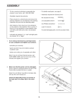
View all ProForm Power 1080 Treadmill manuals
Add to My Manuals
Save this manual to your list of manuals |
Page 13 highlights
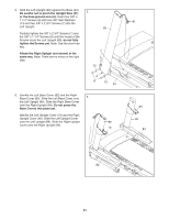
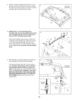
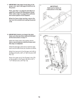
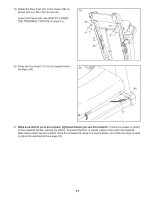
9. Set the console assembly face down on a soft surface to avoid scratching the console assem- 9 bly. Remove the two Screws (A). Next, lift off the Crossbar (93). Discard the two Screws. Console Assembly A 93 10. IMPORTANT: To avoid damaging the Crossbar (93), do not use power tools and do 10 not overtighten the #10 x 3/4" Screws (9) or the #10 x 3/4" Flat Head Screws (28). Orient the Crossbar (93) as shown. Attach the Crossbar to the Handrails (87, 88) with two #10 x 3/4" Flat Head Screws (28), two #10 x 3/4" Screws (9), and two 1/4" Star Washers (35) as shown. Start all four Screws, and then tighten them. 93 9 28 35 88 9 28 35 87 11. With the help of a second person, hold the console assembly near the Left Handrail (88). 11 Connect the Upright Wire (81) to the console wire. See the inset drawing. The connectors should slide together easily and snap into place. If they do not, turn one connector and try again. IF YOU DO NOT CONNECT THE CONNECTORS PROPERLY, THE CONSOLE MAY BECOME DAMAGED WHEN YOU TURN ON THE POWER. Remove the wire tie from the Upright Wire. Console Wire 81 13 Console Assembly Console Wire 81 Wire Tie 88
-
 1
1 -
2
-
3
-
4
-
5
-
6
-
7
-
 8
8 -
 9
9 -
 10
10 -
 11
11 -
 12
12 -
 13
13 -
 14
14 -
 15
15 -
 16
16 -
 17
17 -
 18
18 -
19
-
20
-
21
-
22
-
23
-
24
-
25
-
26
-
27
-
28
-
29
-
30
-
31
-
32
-
33
-
34
-
35
-
36
-
37
-
38
-
39
-
40
 |
 |
