ProForm Xp 130 Elliptical English Manual - Page 6
left Crank Hub. Next, insert four Hub Screws 87 into
 |
View all ProForm Xp 130 Elliptical manuals
Add to My Manuals
Save this manual to your list of manuals |
Page 6 highlights
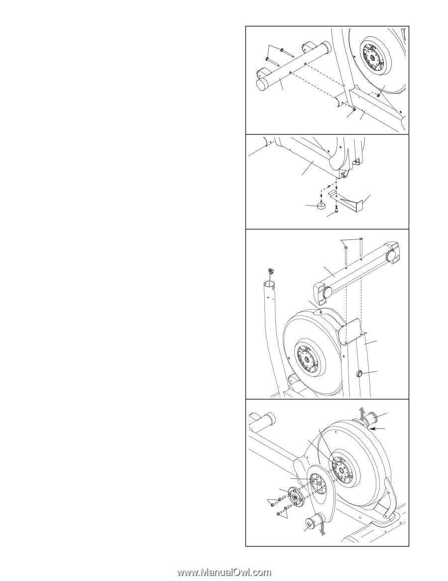
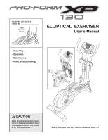
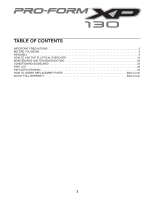
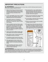
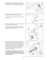
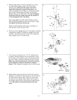
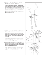
1. While another person lifts the Base (1), attach the Front Stabilizer (6) to the Base with two M10 x 80mm Carriage Bolts (82) and two M10 Nylon Locknuts (81). 1 82 2. Remove the indicated screw and bracket from the 2 Base (1). Discard the screw and the bracket. Next, turn the Base Foot (26) into the Base (1) as far as possible. 3. Attach the Rear Stabilizer (7) to the Frame (2) with two M10 x 127mm Button Screws (83). 3 Next, hold the handle on the Frame (2), press the Latch Button (68), and lower the Frame until the Rear Stabilizer (7) is resting on the floor. 81 6 81 1 1 26 Screw 83 7 Handle Bracket 4. Hold a Hub Cover (75) and a Crank Arm (36) against the left Crank Hub (38). Align the holes in the Hub Cover and the Crank Arm with the unused holes in the left Crank Hub. Next, insert four Hub Screws (87) into the Hub Cover and the Crank Arm, and finger tighten the Hub Screws into the left Crank Hub. Tighten one of the Hub Screws, and then tighten the Hub Screw across from the first Hub Screw. Then, tighten the remaining two Hub Screws. Repeat this step on the right side of the elliptical exerciser; make sure that the Crank Arms (36) are oriented so the Crank Bushing Sleeves (43) are in the positions shown. Note: there are no Pulley Screws (98) on the right side. 4 98 38 36 75 87 87 43 6 2 68 43 36
-
 1
1 -
 2
2 -
 3
3 -
 4
4 -
 5
5 -
 6
6 -
 7
7 -
 8
8 -
 9
9 -
 10
10 -
 11
11 -
 12
12 -
13
-
14
-
15
-
16
-
17
-
18
-
19
-
20
-
21
-
22
-
23
-
24
-
25
-
26
-
27
-
28
 |
 |