Rocketfish RF-G1502 User Manual
Rocketfish RF-G1502 Manual
 |
View all Rocketfish RF-G1502 manuals
Add to My Manuals
Save this manual to your list of manuals |
Rocketfish RF-G1502 manual content summary:
- Rocketfish RF-G1502 | User Manual - Page 1
TV WALL MOUNT RF-TVMLPT01V2 For wood-stud and concrete wall installations Safety information and specifications 2 Tools needed 2 Package contents 3 Installation instructions 4 ASSEMBLY GUIDE Before using your new product, please read these instructions to prevent any damage. - Rocketfish RF-G1502 | User Manual - Page 2
SAFETY INSTRUCTIONS - SAVE THESE INSTRUCTIONS CAUTION: may www.rocketfishproducts.com cause property damage or For customer service, call: personal injury. If you do not understand lbs. (22.6 kg). The wall must be capable of supporting five times the weight of your TV and wall mount combined. - Rocketfish RF-G1502 | User Manual - Page 3
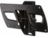
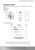
TV WALL MOUNT RF-TVMLPT01V2 Package contents Make sure that you have all the hardware necessary to assemble your new TV wall mount: A TV Bracket (1) H Wall Plate (1) I Template (1) A HAb I TV Hardware Bag Label B C D E F 1 Hardware Qty. M4 × 12 mm screw 4 M4 × 35 mm screw 4 M4 washer 4 - Rocketfish RF-G1502 | User Manual - Page 4
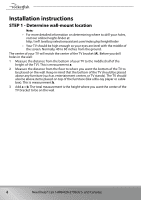
Installation instructions STEP 1 - Determine wall-mount location Note: • For more detailed information on determining where to drill your holes, visit our online height-finder at: http://mf1. - Rocketfish RF-G1502 | User Manual - Page 5
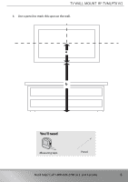
TV WALL MOUNT RF-TVMLPT01V2 4 Use a pencil to mark this spot on the wall. aA bB You'll need Measuring tape Pencil Need help? Call 1-800-620-2790 (U.S. and Canada) 5 - Rocketfish RF-G1502 | User Manual - Page 6
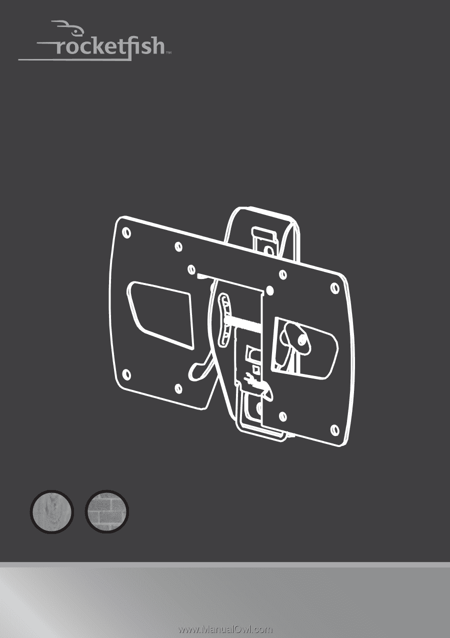
STEP 2 - Option 1: Installing on a wood stud wall Note: Drywall covering the wall must not exceed 5/8" (16 mm). 1 Locate the stud. Verify the center of the stud with an edge-to-edge stud finder. 2 Align the wall plate template (I) at the height you determined in the previous step and make sure that - Rocketfish RF-G1502 | User Manual - Page 7
Note: Minimum wood stud size: Common 2 x 4 in. (51 x 102 mm). Nominal 1.5 x 3.5 in. (38 x 89 mm) TV WALL MOUNT RF-TVMLPT01V2 3 in. (75 mm) You'll need Lag bolt F (2) Level Edge-to edge stud finder Template (I) Wall plate (H) Drill Pencil 7/32" wood drill bit 1/2" socket wrench Tape Need - Rocketfish RF-G1502 | User Manual - Page 8
firm against the TV bracket. CAUTION: Avoid potential injuries or property damage! DO NOT over-tighten the lag bolts (F). *Not included. Call Customer Service to have the Fischer UX10 x 60 concrete anchor kit (Kit# CMK1) shipped directly to you. 8 Need help? Call 1-800-620-2790 (U.S. and Canada - Rocketfish RF-G1502 | User Manual - Page 9
Note: Minimum solid concrete thickness: 8 in. (203 mm) Minimum concrete block size: 8 x 8 x 16 in. (203 x 203 x 406 mm) * Note: Not included. Call Customer Service to have the Fischer UX10 x 60 concrete anchor kit (Kit# CMK1) shipped directly to you. You'll need Lag bolt F (2) Level Hammer Drill - Rocketfish RF-G1502 | User Manual - Page 10
screen from damages and scratches. 2 If your TV has a table-top stand attached, remove the stand. See the documentation that came with your TV for instructions. 3 Temporarily lay the TV bracket (A) on the back of your TV. 4 Align the screw holes in the TV bracket with the mounting screw holes on - Rocketfish RF-G1502 | User Manual - Page 11
damage, make sure that there are adequate threads to secure the brackets to your TV. If you encounter resistance, stop immediately and contact customer service. Use the shortest screw and spacer combination to accommodate your TV. Using hardware that is too long may damage your TV. However, using - Rocketfish RF-G1502 | User Manual - Page 12
STEP 5 - Option 1: Attaching the mounting hardware to TVs with a flat back 1 Place the washers (D) over the holes in the TV bracket (A) that align with the screw holes on the back of your TV, then insert the screws (B) through the washers and the TV bracket. NOTE: If the hole pattern on your TV is - Rocketfish RF-G1502 | User Manual - Page 13
TV WALL MOUNT RF-TVMLPT01V2 STEP 5 - Option 2: Attaching the mounting hardware to TVs with irregular or obstructed backs 1 Place the spacers (E) overtop of the screw holes on the back of your TV. 2 Align the holes on the TV bracket (A) with the spacers on the back of your TV. Place the washers (D) - Rocketfish RF-G1502 | User Manual - Page 14
STEP 6 - Mounting the TV to the wall bracket 1 Mount the TV by fitting the TV bracket (A) over the top lip of the wall plate (H). 2 Secure the TV bracket (A) by pressing the bottom of the TV to the wall bracket (H) until you hear an audible click. HEAVY! You will need assistance with this step. A - Rocketfish RF-G1502 | User Manual - Page 15
TV WALL MOUNT RF-TVMLPT01V2 STEP 7 - Adjusting the tension and the tilt angle • If necessary, adjust the tilt angle by loosening the knob on the right-side of the TV bracket, then adjusting the tilt of the TV. Retighten the knob. TILT Need help? Call 1-800-620-2790 (U.S. and Canada) 15 - Rocketfish RF-G1502 | User Manual - Page 16
bottom of the TV bracket (A), then pull out on the bottom of the TV. 2 Lift the TV up and away from the wall. For customer service, call: 1-800-620-2790 16 Need help? Call 1-800-620-2790 (U.S. and Canada) - Rocketfish RF-G1502 | User Manual - Page 17
TV WALL MOUNT RF-TVMLPT01V2 Need help? Call 1-800-620-2790 (U.S. and Canada) 17 - Rocketfish RF-G1502 | User Manual - Page 18
18 Need help? Call 1-800-620-2790 (U.S. and Canada) - Rocketfish RF-G1502 | User Manual - Page 19
TV WALL MOUNT RF-TVMLPT01V2 Need help? Call 1-800-620-2790 (U.S. and Canada) 19 - Rocketfish RF-G1502 | User Manual - Page 20
Part # 6907-002078 00 www.rocketfishproducts.com (800) 620-2790 ROCKETFISH is a trademark of Best Buy and its affiliated companies. Registered in some countries. Distributed by Best Buy Purchasing, LLC 7601 Penn Ave South, Richfield, MN 55423 U.S.A. ©2014 Best Buy. All rights reserved. Made in China
-
 1
1 -
 2
2 -
 3
3 -
 4
4 -
 5
5 -
 6
6 -
 7
7 -
8
-
9
-
10
-
11
-
12
-
13
-
14
-
15
-
16
-
17
-
18
-
19
-
20
 |
 |
TV WALL MOUNT
RF-TVMLPT01V2
ASSEMBLY GUIDE
Safety information and specifications
......................
2
Tools needed
......................................................................
2
Package contents
.............................................................
3
Installation instructions
.................................................
4
For wood-stud and concrete
wall installations
Before using your new product, please read these instructions to prevent any damage.