Ryobi A25RT03 Operation Manual
Ryobi A25RT03 Manual
 |
View all Ryobi A25RT03 manuals
Add to My Manuals
Save this manual to your list of manuals |
Ryobi A25RT03 manual content summary:
- Ryobi A25RT03 | Operation Manual - Page 1
ROUTER TABLE TABLE À TOUPIE MESA FRESADORA 3 2 1 0 1 Inch A25RT03 inch 3 2 1 0 1 Inch TABLE OF CONTENTS General Safety Rules 2-3 Specific Safety Rules 3 Symbols 4 Electrical 5 Features 6-7 Assembly 8-15 Operation 16-18 Maintenance 19 Parts Ordering and Service manual - Ryobi A25RT03 | Operation Manual - Page 2
READ ALL INSTRUCTIONS KNOW YOUR POWER TOOL. Carefully read the router table operator's manual and the manual for the particular router you are its operation. A guard or other part that is damaged must be properly repaired or replaced by an authorized service center to avoid risk of personal injury - Ryobi A25RT03 | Operation Manual - Page 3
the risk of personal injury. Instructions for safe use of accessories are included with the accessory. SPECIFIC SAFETY RULES FOR YOUR OWN SAFETY, read this router table operator's manual and the router manual before operating the router or using the router table. ALWAYS USE THE ARTICULATING - Ryobi A25RT03 | Operation Manual - Page 4
SYMBOL NAME DESIGNATION/EXPLANATION Safety Alert Indicates a potential personal injury hazard. Read Operator's Manual Eye Protection To reduce the risk of injury, user must read and understand operator's manual before using this product. Always wear eye protection with side shields marked to - Ryobi A25RT03 | Operation Manual - Page 5
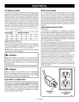
no-load speed of this product depends on the router you are using. This speed is not constant and support one power product may not be able to support two or three products. GROUNDING INSTRUCTIONS qualified electrician or service personnel if the grounding instructions are not completely understood - Ryobi A25RT03 | Operation Manual - Page 6
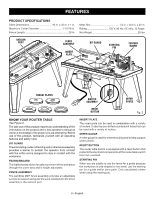
for mitered routing and to help support wider pieces. RESET BUTTON The router table switch is equipped with a reset button that protects the electronic components of the router table switch box from overload. STARTING PIN When you are unable to use the fence for a guide because the workpiece is odd - Ryobi A25RT03 | Operation Manual - Page 7
is intended to prevent unauthorized and possible hazardous use by children and others. TO TURN YOUR ROUTER TABLE ON: Plug the router into either switch box outlet on the router table and plug the router table into a 120 volt grounded outlet. With the switch key inserted into the switch, lift the - Ryobi A25RT03 | Operation Manual - Page 8
the loose parts list are included. WARNING: Do not use this product if any parts on the Loose Parts List are already assembled to your product when you unpack it. Parts on this be securely in place before using the router table. Failure to do so could result in serious personal injury. 8 - - Ryobi A25RT03 | Operation Manual - Page 9
16 B. Hex Key 1 C. Starting Pin 1 D. Under Table Guard Screw 6 E. Router Insert Plate Screws (5/16-18 x 3/4 in 3 F. Router Insert Plate Screws (10-24 x 5/8 in 3 G. Router Insert Plate Screws (10-32 x 5/8 in 3 H. Table Leg 4 I. Table Top 1 J. Switch Box 1 K. Carriage Bolt Washer 2 NOTE - Ryobi A25RT03 | Operation Manual - Page 10
with the three holes on the outside of the front rail, this is the rail that is already installed on the front underside of the router table. Insert the switch box screws through the holes in the switch box and through the holes in the front rail. Install the nuts on the - Ryobi A25RT03 | Operation Manual - Page 11
pilot hole large enough for the depth adjustment tool (not included with router table, but may be included with your router) to pass though so through table depth adjustments can be made. Figure 8 Key: RD: RIDGID R2930, R22002 RY: Ryobi R163K, R163GK ML: Milwaukee 5615-20, 5616-20 PC1: Porter-Cable - Ryobi A25RT03 | Operation Manual - Page 12
ASSEMBLY BRAND MODEL BASE TYPE FASTENER SIZE INSERT PLATE HOLES USED Ryobi R163GK Fixed 5/16-18 x 3/4 in. B1, B2, B4 3 Ryobi R160 Fixed 5/16-18 x 3/4 in. B1, B2, B4 3 Ryobi R161K Fixed 5/16-18 x 3/4 in. B1, B2, B4 3 Ryobi R162K Fixed 5/16-18 x 3/4 in. B1, B2, B4 3 Ryobi - Ryobi A25RT03 | Operation Manual - Page 13
FENCE LOCK KNOB WASHER Fig. 12 FENCE FENCE LOCK KNOBS ASSEMBLY ATTACHING THE FENCE ASSEMBLY See Figure 13. n Unplug the router table and/or the router. Place the router table right side up with the back edge closest to you. n Slide the carriage bolt washers onto the carriage bolts. Slide - Ryobi A25RT03 | Operation Manual - Page 14
the fence lock knobs. INSERTING THE STARTING PIN See Figure 16. Remove the starting pin from the blister pack. Place the starting pin on the router table and use it as a pivot point when cutting small, odd-shaped pieces. 3 2 NOTE: It is not necessary to use the fence0 wh1 en you are - Ryobi A25RT03 | Operation Manual - Page 15
, insert the top front of clamp through the opening in the router table leg. Tighten clamp securely. MOUNTING THE ROUTER TABLE TO A WORK BENCH See Figure 20. n Unplug the router table and/or the router. Place the router table right side up on a sturdy work surface; e.g., leg stand, workbench - Ryobi A25RT03 | Operation Manual - Page 16
the starting pin for edging patterned surfaces on wood and wood composition materials WARNING: The router or router table should never be connected to a power supply when you are assembling parts, making adjustments, installing or removing cutters, cleaning, or when not in use. Disconnecting the - Ryobi A25RT03 | Operation Manual - Page 17
operator's manual for the router and router table. n Plug the router table power cord into a power source. n Always control the power to the router with the router table switch whenever the router is mounted on the table. n Always plug the router into either of the router table switched outlets - Ryobi A25RT03 | Operation Manual - Page 18
router operator's manual for adjusting the depth of cut. 3 2 1 0 1 Inch ADJUSTING THE MITER GAUGE See Figure 24. n Unplug the router table and/or the router 25. The fence enables you to support and guide the workpiece. n Unplug the router table and/or the router. n Loosen the fence lock knobs. - Ryobi A25RT03 | Operation Manual - Page 19
MAINTENANCE WARNING: When servicing, use only identical replacement parts. Use of any other parts could create a hazard possible serious injuries. GENERAL MAINTENANCE Avoid using solvents when cleaning plastic parts. Most plastics are susceptible to damage from various types of commercial solvents - Ryobi A25RT03 | Operation Manual - Page 20
état. Utiliser exclusivement un cordon d'une capacité suffisante pour supporter le courant de fonctionnement de l'outil. Un cordon de capacité propres pour accroître la sécurité et les performances. Suivre les instructions de lubrification et de changement d'accessoires. DÉBRANCHER TOUS LES OUTILS - Ryobi A25RT03 | Operation Manual - Page 21
accessoire non recommandé peut présenter un risque de blessure. Les instructions de sécurité d'utilisation sont fournies avec les accessoires. RÈGLES TOUJOURS MAINTENIR FERMEMENT EN PLACE LA PIÈCE À TRAVAILLER CONTRE LA TABLE ET LE GUIDE. SI LE CORDON D'ALIMENTATION EST ENDOMMAGÉ, il doit être - Ryobi A25RT03 | Operation Manual - Page 22
SYMBOLES Les termes de mise en garde suivants et leur signification ont pour but d'expliquer le degré de risques associé à l'utilisation de ce produit. SYMBOLE SIGNAL SIGNIFICATION DANGER : Indique une situation dangereuse qui, si elle n'est pas évitée, aura pour conséquences des blessures - Ryobi A25RT03 | Operation Manual - Page 23
branchés sur une prise triphasée compatible avec la fiche de l'produit. Lors cordon prolongateur d'une capacité suffisante pour supporter l'appel de courant de l'produit. Un Consulter un électricien qualifié ou le personnel de service si les instructions de mise à la terre ne sont pas bien comprises - Ryobi A25RT03 | Operation Manual - Page 24
compatible avec divers types de toupies. Il a pré-a entraîné aussi des trous noyé qui peuvent être utilisés avec une assortiment de toupies. GUIDE D'ONGLET Un guide te de commutateur de table de routeur de la surcharge. CHEVILLE DE DÉPART Quand vous ne pouvez pas utiliser le guide pour guider lapièce - Ryobi A25RT03 | Operation Manual - Page 25
CARACTÉRISTIQUES PLAQUES À OUVERTURE Cinq plaques à ouverture sont fournies avec la table à toupie. La plaque à gorge procure un support stable autour du fer et empêche que des objets puissent tomber dans l'ouverture et endommager la broche. ORIFICE D'ASPIRATION Les ports de poussière - Ryobi A25RT03 | Operation Manual - Page 26
de cet avertissement peut causer un démarrage accidentel, entraînant des blessures graves. AVERTISSEMENT : Les protecteur inférieurs bien montés en place avant d'utiliser la table à toupie. Sinon des blessures graves pourraients'ensuivre. 8 - Français - Ryobi A25RT03 | Operation Manual - Page 27
carr 2 M. Protecteurs sous table 2 N. Plaque à ouverture 5 O. Guide d'onglet 1 P. Ensemble de guide 1 Q. Bouton de verrouillage du guide 2 R. Cale-guide 1 S. Boulon à cale-guide 2 T. Rondelle de bouton de verrouillage du guide 2 U. Bouton de cale-guide 2 V. Manual de utilisation (non - Ryobi A25RT03 | Operation Manual - Page 28
, il faut fixer la boîte d'interrupteur, les protecteurs sous table, les pieds, l'ensemble toupie/plaque d'insertion, l'ensemble guide, le cale-guide, la plaque à gorge et la goupille de départ et installer la jauge à onglets sur la table à toupie. FIXER LA BOÎTE D'INTERRUPTEUR Voir la figure 5. La - Ryobi A25RT03 | Operation Manual - Page 29
outil de réglage de la hauteur de coupe (non inclus avec la table à toupie, mais peut être inclus avec la toupie) pour régler la hauteur de coupe sur la table. Les abréviations figure 8 signifiant : RD : RIDGID R2930, R22002 RY : Ryobi R163K, R163GK ML : Milwaukee 5615-20, 5616-20 PC1 : Porter-Cable - Ryobi A25RT03 | Operation Manual - Page 30
R22002 Fixe 10-32 x 16 mm (5/8 po) A1, A3, A5 3 Ryobi R163GK Fixe 5/16-18 x 19 mm (3/4 po) B1, B2, B4 3 Ryobi R160 Fixe 5/16-18 x 19 mm (3/4 po) B1, B2, B4 3 Ryobi R161K Fixe 5/16-18 x 19 mm (3/4 po) B1, B2, B4 3 Ryobi R162K Fixe 5/16-18 x 19 mm (3/4 po) B1, B2, B4 - Ryobi A25RT03 | Operation Manual - Page 31
part détaché jusqu'à ce que tous ajustements ont été faits. PLAQUE D'INSERTION NIVELER LA PLAQUE D'INSERTION Voir la figure 12. 3 n Débrancher la toupie et la table 1 Inch FIXER L'ENSEMBLE GUIDE Voir la figure 13. n Débrancher la toupie et la table à toupie . n Placer la table à toupie, le côté - Ryobi A25RT03 | Operation Manual - Page 32
couvrir le coupeur. Aussi, n'utilisez que des fers avec guide quand la cheville de départ est employée. n Débrancher la toupie et la table à toupie . n Mettez la cheville de départ dans le trou taraudé à ladroite de l'ouverture de la table à toupie. n Appuyer sur la goupille pour la mettre en - Ryobi A25RT03 | Operation Manual - Page 33
de travail stable et robuste, comme par exemple, un support, un établi ou un travailler la table. n Faites un repère des trous avec un crayon. n Enlevez la table à toupie. n Percez quatre trous dans la surface de travail. n Remettez la table à toupie sur la surface de travail, alignez les trous - Ryobi A25RT03 | Operation Manual - Page 34
pour approcher les surfaces modelées sur le bois et les matériels de composition de bois AVERTISSEMENT : Votre toupie ou table à toupie ne doit table à toupie. Ne jamais brancher une toupie installée sur une table à toupie dans une autre source de courant. n Placer le guide d'entrée et le guide - Ryobi A25RT03 | Operation Manual - Page 35
pièce en place après la coupe. La position « 0 » sur l'échelle du guide indique le centre de l'ouverture de gorge de la table. n Vérifier que tous les réglages de la toupie sont bien verrouillés avant de brancher la table à toupie à une source de courant. n Le couteau tourne vers la gauche (lorsque - Ryobi A25RT03 | Operation Manual - Page 36
D'ONGLET Voir la figure 24. n Débrancher la toupie et la table à toupie. n Desserrez le bouton du guide d'onglet. n Tournez le guide d'onglet à l'angle désiré. n Serrez le bouton du guide d'onglet. 3 2 1 0 1 Inch POSITIONNEMENT DU GUIDE Voir la figure 25. Suivez ces directives pour positionner le - Ryobi A25RT03 | Operation Manual - Page 37
ENTRETIEN AVERTISSEMENT : Utiliser exclusivement des pièces d'origine pour les réparations. L'usage de toute autre pièce pourrait créer une situation dangereuse ou endommager l'outil. AVERTISSEMENT : Toujours porter une protection oculaire avec écrans latéraux certifiée conforme à la norme ANSI Z87 - Ryobi A25RT03 | Operation Manual - Page 38
ELÉCTRICA. Lea con cuidado la fresadora pospone manual de usario y el manual para la fresadora particular que usted utiliza. Aprenda los flojos, corbata ni alhajas. Podrían engancharse y tirar de usted hacia partes en movimiento. Se recomiendan guantes y calzado antiderrapantes al trabajar al aire - Ryobi A25RT03 | Operation Manual - Page 39
instrucciones para su uso sin riesgos. REGLAS DE SEGURIDAD ESPECÍFICAS PARA SU PROPIA SEGURIDAD, lea este manual del router de la mesa del operador y el manual del router antes de hacer funcionar el router o el uso de la mesa fresado SIEMPRE UTILICE EL GUARDIA DE CORTADOR. CUANDO SE USA EL - Ryobi A25RT03 | Operation Manual - Page 40
Volts Amperes Hertz Minutos Corriente alterna Velocidad en vacío Por minuto Para reducir el riesgo de lesiones, el usuario debe leer y comprender el manual del operador antes de usar este producto. Siempre póngase protección ocular con protección lateral con la marca de cumplimiento de la norma - Ryobi A25RT03 | Operation Manual - Page 41
antes de usarlos. Si están dañados, reemplácelos de inmediato. Nunca utilice la producto con un cable dañado, ya que si toca la parte dañada puede sufrir una descarga eléctrica, con las consecuentes lesiones graves. CONEXIÓN ELÉCTRICA Esta producto debe conectarse únicamente a una línea de voltaje - Ryobi A25RT03 | Operation Manual - Page 42
FRESADORA Vea la figura 2. Para usar este producto con la debida seguridad se debe comprender la información indicada en la herramienta misma y en este manual, y se debe comprender también el trabajo que intenta realizar. Antes de usar este producto, familiarícese con todas las características de - Ryobi A25RT03 | Operation Manual - Page 43
CARACTERÍSTICAS PLACAS DE GARGANTA Con su mesa fresadora se incluyen cinco placas de garganta. La placa de garganta proporciona una superficie estable alrededor de la fresa y evita que se caigan objetos a través de la garganta y se dañe el husillo. ACCESORIO PARA ASPIRADORA Los puertos del polvo - Ryobi A25RT03 | Operation Manual - Page 44
. ADVERTENCIA: Si hay piezas dañadas o faltantes, no utilice esta herramiento sin haber reemplazado todas las piezas. Usar este producto con partes dañadas o faltantes puede causar lesiones serias al operador. ADVERTENCIA: No intente modificar este producto ni hacer accesorios no recomendados para - Ryobi A25RT03 | Operation Manual - Page 45
de la guía 2 R. Peine de sujeción 1 S. Tornillo de peine de sujeción 2 T. Arandela de perilla de bloqueo de la guía 2 U. Perilla de peine de sujeción 2 V. Manual del operador (no se ilustra) NOTA: Los artículos de la A a la G están incluidos en un envase al vacío por separado 9 - Español - Ryobi A25RT03 | Operation Manual - Page 46
delantera debe tener el lado con el extremo abierto de cara a la parte posterior de la mesa para fresadora. Alinee los tres agujeros de las protecciones bajo la mesa con los agujeros de la mesa. El protector delantero de la parte inferior de la mesa se conecta a través del riel delantero y en la - Ryobi A25RT03 | Operation Manual - Page 47
parte delantera, y las patas sin las etiquetas de advertencia deben colocarse en la parte 8 que significa: RD: RIDGID R2930, R22002 RY: Ryobi R163K, R163GK ML: Milwaukee 5615-20, 5616-20 inserto del router del envase al vacío. Use estos tornillos para conectar la placa del inserto del router. n - Ryobi A25RT03 | Operation Manual - Page 48
Cable 892 Porter Cable 893PK Porter Cable 7529 Porter Cable 8529 RIDGID R2930 RIDGID R22002 Ryobi R163GK Ryobi R160 Ryobi R161K Ryobi R162K Ryobi R163K Ryobi R165U Ryobi R175 Ryobi RE175 Ryobi RE180PL/PL1/PL1G Skil 1810 Skil 1825 TIPO DE BASE Fija Fija Fija Fija Fija - Ryobi A25RT03 | Operation Manual - Page 49
, fije la fresadora a la placa de inserción con los agujeros guía de cara a la fresadora y la muesca en la placa de inserción de cara a la parte posterior de la mesa para fresadora. PLACA DE INSERCIÓN NOTA: Al conectar placa de inserción al fresadora, la marca segura los hoyos en el fresadora - Ryobi A25RT03 | Operation Manual - Page 50
la ranura de la 2plac3a de inserción hasta que entre en su lugar. 1 0 n Para quitarla, empuje la placa de la ga1rganta hacia afuera desde la parte inferior de la placa de Inch inserción. MONTAJE DEL PEINE DE SUJECIÓN Vea la figura 15. n Quite la fresadora y el mesa fresadora. n Coloque los - Ryobi A25RT03 | Operation Manual - Page 51
coloque la barra de la guía de ingletes en la ranura cerca de la parte delantera de la mesa con el puntero a la derecha. INSTALACION DE LA ACCESORIO , banco de trabajo, mesa, etc.). n Con una prensa de mano, pase la parte delantera superior de la prensa de mano a través de la abertura en la pata - Ryobi A25RT03 | Operation Manual - Page 52
de alimentación. FORMA DE EFECTUAR OPERACIONES DE FRESADO Vea las figuras 21 a 23. Observe las siguientes reglas al usar la fresadora: n Lea todo el Manual del Operador de la fresadora y la mesa para fresadora. n Conecte el cordón de corriente de la mesa de la fresadora en un suministro de corriente - Ryobi A25RT03 | Operation Manual - Page 53
rota en el sentido contrario a las agujas del reloj (vista desde la parte superior de la mesa) en la mesa de la fresadora. Siempre avance la producida por el corte. Siempre use una llave. n Consulte el Manual del Operador de la fresadora para conocer el procedimiento adecuado para retirar/instalar - Ryobi A25RT03 | Operation Manual - Page 54
FUNCIONAMIENTO AJUSTE DE LA PROFUNDIDAD DE CORTE Consulte el manual del operador de la fresadora para ajustar la profundidad del corte. AJUSTE DEL CALIBRE DE INGLETE Vea la figura 24. n Quite la fresadora y el mesa - Ryobi A25RT03 | Operation Manual - Page 55
de vidrio, paneles de yeso para paredes, compuestos de resanar o yeso, están sujetas a desgaste acelerado y posible fallo prematuro porque las partículas y limaduras de fibra de vidrio son altamente abrasivas para los cojinetes, escobillas, conmutadores, etc. Por consiguiente, no recomendamos el uso - Ryobi A25RT03 | Operation Manual - Page 56
OPERATOR'S MANUAL/ROUTER TABLE MANUEL D'UTILISATION / TABLE À TOUPIE MANUAL DEL OPERADOR/MESA FRESADORA A25RT03 To request service, purchase replacement parts, locate an Authorized Service Center and obtain Customer or Technical Support: Visit www.ryobitools.com or call 1-800-525-2579 If any parts
-
 1
1 -
 2
2 -
 3
3 -
 4
4 -
 5
5 -
 6
6 -
 7
7 -
8
-
9
-
10
-
11
-
12
-
13
-
14
-
15
-
16
-
17
-
18
-
19
-
20
-
21
-
22
-
23
-
24
-
25
-
26
-
27
-
28
-
29
-
30
-
31
-
32
-
33
-
34
-
35
-
36
-
37
-
38
-
39
-
40
-
41
-
42
-
43
-
44
-
45
-
46
-
47
-
48
-
49
-
50
-
51
-
52
-
53
-
54
-
55
-
56
 |
 |

OPERATOR’S MANUAL
MANUEL D’UTILISATION
MANUAL DEL OPERADOR
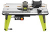
ROUTER TABLE
TABLE À TOUPIE
MESA FRESADORA
A25RT03
WARNING:
To reduce the
risk of injury, the user must read and
understand the operator’s manual
before using this product.
ADVERTENCIA:
Para reducir
el riesgo de lesiones, el usuario debe leer
y comprender el manual del operador
antes de usar este producto.
AVERTISSEMENT :
Pour
réduire les risques de blessures,
l’utilisateur doit lire et veiller à bien
comprendre le manuel d’utilisation avant
d’employer ce produit.
TABLE OF CONTENTS
General Safety Rules
.......................
2-3
Specific Safety Rules
.........................
3
Symbols
..............................................
4
Electrical
.............................................
5
Features
...........................................
6-7
Assembly
.......................................
8-15
Operation
.....................................
16-18
Maintenance
.....................................
19
Parts Ordering
and Service
.........................
Back page
TABLE DES MATIÈRES
Règles de sécurité générales
..........
2-3
Règles de sécurité particulières
.........
3
Symboles
............................................
4
Caractéristiques électriques
...............
5
Caractéristiques
..............................
6-7
Assemblage
...................................
8-15
Utilisation
.....................................
16-18
Entretien
...........................................
19
Commande de pièces
et dépannage
....................
Page arrière
ÍNDICE DE CONTENIDO
Reglas de seguridad generales
.......
2-3
Reglas de seguridad específicas
.......
3
Símbolos
............................................
4
Aspectos eléctricos
............................
5
Características
................................
6-7
Armado
..........................................
8-15
Funcionamiento
...........................
16-18
Mantenimiento
..................................
19
Pedidos de piezas
y servicio
.......................
Pág. posterior
SAVE THIS MANUAL FOR
FUTURE REFERENCE
CONSERVER CE MANUEL
POUR FUTURE RÉFÉRENCE
GUARDE ESTE MANUAL
PARA FUTURAS CONSULTAS
Inch
1
0
1
2
3
Inch
1
0
1
2
3
inch