Ryobi P881 User Manual 5 - Page 6
Symbols, Features - impact driver
 |
View all Ryobi P881 manuals
Add to My Manuals
Save this manual to your list of manuals |
Page 6 highlights
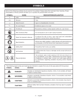
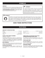
SYMBOLS SERVICE Servicing requires extreme care and knowledge and should be performed only by a qualified service technician. For service we suggest you return the product to the nearest AUTHORIZED SERVICE CENTER for repair. When servicing, use only identical replacement parts. WARNING: To avoid serious personal injury, do not attempt to use this product until you read thoroughly and understand completely the operator's manual. If you do not understand the warnings and instructions in the operator's manual, do not use this product. Call Ryobi customer service for assistance. WARNING: The operation of any power tool can result in foreign objects being thrown into your eyes, which can result in severe eye damage. Before beginning power tool operation, always wear safety goggles or safety glasses with side shields and, when needed, a full face shield. We recommend Wide Vision Safety Mask for use over eyeglasses or standard safety glasses with side shields. Always use eye protection which is marked to comply with ANSI Z87.1. SAVE THESE INSTRUCTIONS FEATURES PRODUCT SPECIFICATIONS Motor 18 Volt DC Coupler 1/4 in. Gear Train One Speed Switch Variable Speed KNOW YOUR IMPACT DRIVER See Figure 1, page 10. The safe use of this product requires an understanding of the information on the product and in this operator's manual as well as a knowledge of the project you are attempting. Before use of this product, familiarize yourself with all operating features and safety rules. BIT STORAGE When not in use, bits provided with the impact driver can be placed in the storage area located on base of the handle. BLOWS PER MINUTE This tool features an impact speed of 3,500 Blows Per Minute (BPM). Blows Per Minute is the number of impacts per minute. No Load Speed 0-2400 r/min. (RPM) Torque 1,200 in.lb. Blows Per Minute 3,500 BPM DIRECTION OF ROTATION SELECTOR (FORWARD/REVERSE/CENTER LOCK) The direction of rotation (forward/reverse/center lock) selector located above the switch trigger will change the direction of bit rotation. LED WORKLIGHT The LED worklight, located under the chuck, illuminates when the switch trigger is depressed. This provides extra light for increased visibility. VARIABLE SPEED This tool has a variable speed switch that delivers higher speed with increased trigger pressure. Speed is controlled by the amount of switch trigger depression. 6 - English
-
 1
1 -
 2
2 -
 3
3 -
 4
4 -
 5
5 -
 6
6 -
 7
7 -
 8
8 -
 9
9 -
 10
10 -
 11
11 -
 12
12 -
13
-
14
-
15
-
16
-
17
-
18
-
19
-
20
-
21
-
22
-
23
-
24
-
25
-
26
-
27
-
28
 |
 |