Ryobi TS1144 Operation Manual - Page 18
Removing/replacing The Throat Plate, Warning, Squaring The Blade To The Fence
 |
View all Ryobi TS1144 manuals
Add to My Manuals
Save this manual to your list of manuals |
Page 18 highlights
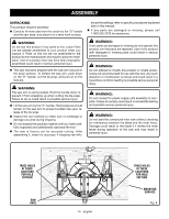
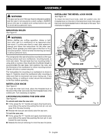
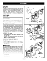
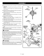
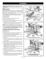
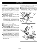
ASSEMBLY REMOVING/REPLACING THE THROAT PLATE See Figure 15. WARNING: The throat plate must be below the miter table. If the throat plate is too high or too low, the workpiece can catch on the uneven edges resulting in binding which could result in serious personal injury. Never operate the saw without a throat plate installed. To remove/replace: Unplug the saw. Remove the screws securing the throat plate. Lift the throat plate from the saw. To reinstall the throat plate, align the holes in the throat plate with the holes in the saw base. Retighten the screws, being careful not to overtighten which can cause the throat plate to bow or bend. NOTE: Many of the illustrations in this manual show only portions of the compound miter saw. This is intentional so that we can clearly show points being made in the illustrations. Never operate the saw without all guards securely in place and in good operating condition. MITER FENCE THROAT PLATE BLADE Fig. 15 SQUARING THE BLADE TO THE FENCE See Figures 16 - 21. Unplug the saw. Pull the saw arm all the way down and engage the lock pin to hold the saw arm in transport position. Loosen the miter lock knob approximately one-half turn and press the detent release button. Rotate the miter table until the scale indicator is positioned at 0°. Release the detent release button, engaging the positive stop notch, then tighten the miter lock knob to secure the miter table. Loosen bevel lock knob and set saw arm at 0° bevel (blade set 90° to miter table). Tighten bevel lock knob. Lay a square flat on the miter table. Place one leg of the square against the fence. Slide the other leg of the square against the flat part of saw blade. NOTE: Make sure that the square contacts the flat part of the saw blade, not the blade teeth. The edge of the square and the saw blade should be parallel as shown in figure 16. If the front or back edge of the saw blade angles away from the square as shown in figures 17 - 18, adjustments are needed. Loosen the fence screw and slide the partial sliding miter fence toward the blade to access the socket head screws securing the left miter fence to the table. SQUARE MITER TABLE VIEW OF BLADE SQUARE WITH FENCE MITER LOCK KNOB Fig. 16 BLADE MITER FENCE SQUARE MITER TABLE VIEW OF BLADE NOT SQUARE WITH FENCE, ADJUSTMENTS ARE REQUIRED Fig. 17 18 - English
-
 1
1 -
2
-
3
-
4
-
5
-
6
-
7
-
8
-
9
-
10
-
11
-
12
-
 13
13 -
 14
14 -
 15
15 -
 16
16 -
 17
17 -
 18
18 -
 19
19 -
 20
20 -
 21
21 -
 22
22 -
 23
23 -
24
-
25
-
26
-
27
-
28
-
29
-
30
-
31
-
32
-
33
-
34
-
35
-
36
-
37
-
38
-
39
-
40
-
41
-
42
-
43
-
44
-
45
-
46
-
47
-
48
-
49
-
50
-
51
-
52
-
53
-
54
-
55
-
56
-
57
-
58
-
59
-
60
-
61
-
62
-
63
-
64
-
65
-
66
-
67
-
68
-
69
-
70
-
71
-
72
-
73
-
74
-
75
-
76
-
77
-
78
-
79
-
80
-
81
-
82
-
83
-
84
-
85
-
86
-
87
-
88
-
89
-
90
-
91
-
92
 |
 |
