Samsung NE59M4310SS/AA Installation Guide - Page 9
Caution
 |
View all Samsung NE59M4310SS/AA manuals
Add to My Manuals
Save this manual to your list of manuals |
Page 9 highlights
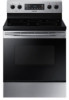
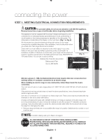
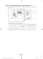
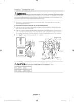
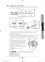
STEP 4. INSTALLING THE CONDUIT Remove the conduit connection plate from the rear of the drawer body and rotate it as shown below. The conduit hole (11/8") must be used. " 11/8 " 13/8 02 CONNECTING THE POWER " 13/8 1. Prepare the conduit cord shown in Figure 1. 2. Install the conduit cord as shown in Figure 2. Figure 1 1" 3/8" 1" 3/8" " 11/8 31/2" 3 wire 31/2" 4 wire Knockout surface Conduit connection plate Figure 2 Ring Body Strain relief For conduit installations, insert the strain relief (not included) into the conduit hole (11/8"). Then thread the conduit cord through the body of the strain relief and fasten the ring. Reinstall the bracket. Installing a 3-wire conduit • Aluminum building wire may be used but it must be rated for the correct amperage and voltage to make the connection. Connect wires according to Step 4 depending on the number of wires. • Wire used, location and enclosure of splices, etc., must conform to good wiring practices and local codes. 1. Loosen the 3 lower terminal screws from the terminal block. 2. Insert the center bare wire (white/neutral) tip through the bottom center terminal block opening. On certain models, the wire will need to be inserted through the ground strap opening and then into the bottom center block opening. Neutral terminal Black Ground strap White Red 3. Insert the two side bare wire tips into the lower left and the lower right terminal block openings. Live 1 Live 2 4. Tighten the screws until the wire is firmly secured (35 to 50 inch-lbs.). Do not over-tighten the screws since it could damage the wires. 5. Go to step 5 on page 10 and proceed with the installation. Black White Red Wire tips CAUTION CAUTION You must check voltage after connecting power cord. Live 1 - Neutral Live 2 - Neutral Live 1 - Live 2 120 V 120 V 208 V / 240 V English - 9 Install_30_Electric_Range_USA_DG68-00108G-09_EN+MES.indb 9 2018-07-31 3:48:05
-
 1
1 -
2
-
3
-
 4
4 -
 5
5 -
 6
6 -
 7
7 -
 8
8 -
 9
9 -
 10
10 -
 11
11 -
 12
12 -
 13
13 -
 14
14 -
15
-
16
-
17
-
18
-
19
-
20
-
21
-
22
-
23
-
24
 |
 |
