Samsung SCS-2U3100/VER User Manual Ver.f8 (English) - Page 13
Components - Rear View - gps antenna
 |
View all Samsung SCS-2U3100/VER manuals
Add to My Manuals
Save this manual to your list of manuals |
Page 13 highlights
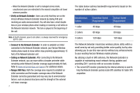
LED Function Description PWR Power • Solid blue: normal • No light: abnormal SYS System connected • Solid blue: normal • Solid red: abnormal GPS GPS signal • Solid blue: normal (GPS is received) • Blinking blue or red: while searching for GPS • No light: abnormal (GPS signal cannot be received, the external GPS antenna is required) WAN WAN (Ethernet) connection • Solid blue: normal • Blinking blue: data communication • No light: abnormal Components - Rear View The rear of the Network Extender provides access to the WAN port, power port, and external GPS antenna. 1. GPS Antenna Port slides to provide access to the external GPS antenna for removal and relocation. • A red GPS LED indicates a GPS signal could not be detected using the internal GPS antenna. The external GPS antenna should be connected. See "External GPS Antenna" on page 13. 2. Heat Vents provide passive ventilation for the Network Extender and allow for dissipation of internally generated heat. Note: The Network Extender needs to remain vertical and in a well-ventilated location. The vertical position allows proper air flow to the internal components. 3. DC 12V Power Port provides power to the Network Extender when connected to the AC power supply and cord (included). Warning!: Only use the provided power cord and supply. Using any other power source may damage the Network Extender. Using Your Device 10
-
 1
1 -
2
-
3
-
4
-
5
-
6
-
7
-
 8
8 -
 9
9 -
 10
10 -
 11
11 -
 12
12 -
 13
13 -
 14
14 -
 15
15 -
 16
16 -
 17
17 -
 18
18 -
19
-
20
-
21
-
22
-
23
-
24
-
25
-
26
-
27
-
28
-
29
-
30
-
31
-
32
-
33
-
34
-
35
-
36
-
37
-
38
-
39
-
40
-
41
-
42
-
43
-
44
-
45
-
46
-
47
-
48
-
49
-
50
-
51
-
52
-
53
-
54
-
55
-
56
-
57
-
58
-
59
-
60
-
61
-
62
-
63
-
64
-
65
-
66
-
67
 |
 |
