Samsung SGH-T429 Service Manual - Page 56
DCS Transmitter
 |
View all Samsung SGH-T429 manuals
Add to My Manuals
Save this manual to your list of manuals |
Page 56 highlights
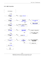
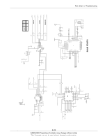
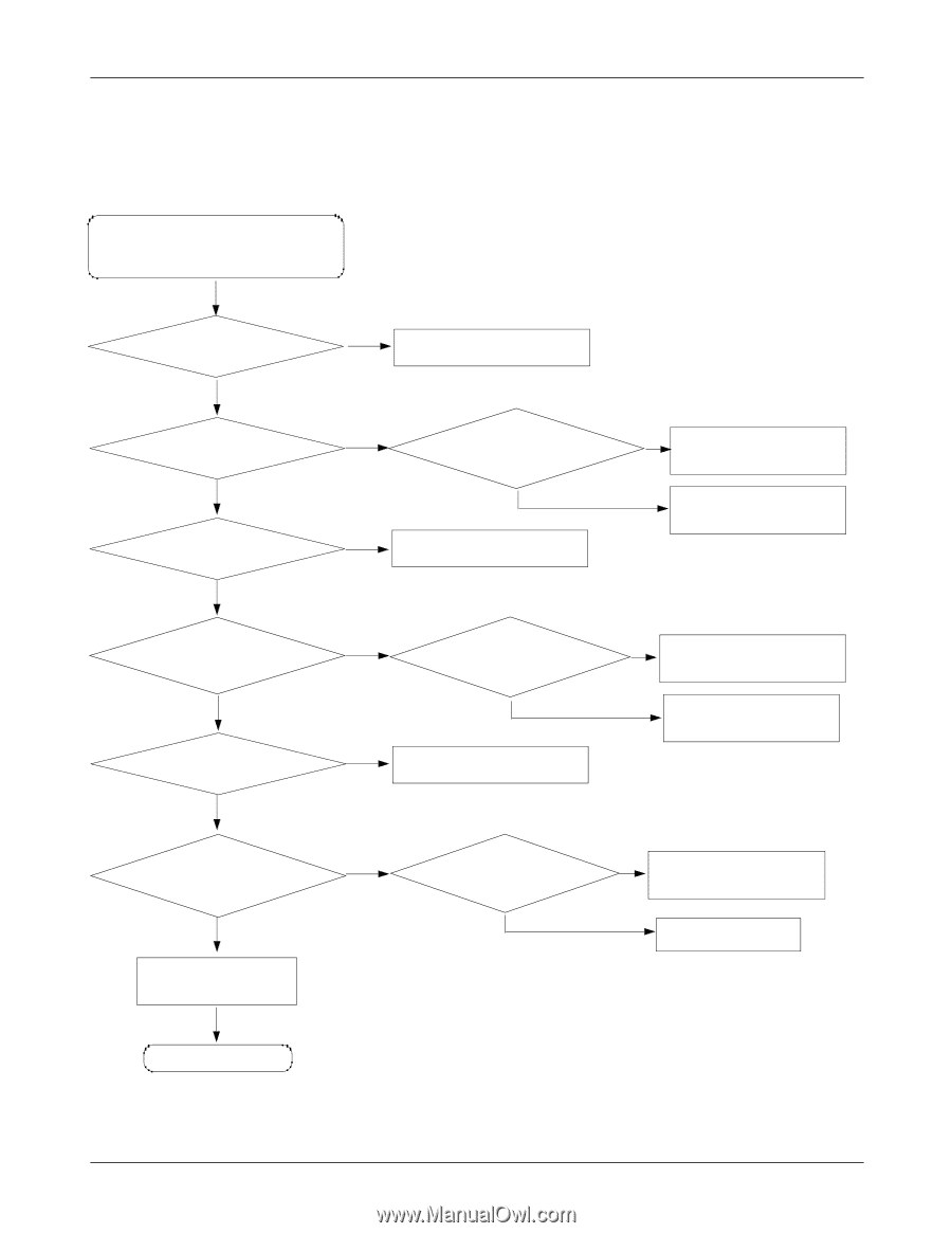
Flow Chart of Troubleshooting 9-15. DCS Transmitter TX ON (5Level) Yes F100 Pin7 >= 20dBm Yes F100 pin3 >= 18dBm Yes PAM100 pin15 >= 18dBm Yes PAM100 pin3 =2.8V RF PSU Part Yes Resolder U101 9-24 SAMSUNG Proprietary-Contents may change without notice This Document can not be used without Samsung's authorization
-
 1
1 -
2
-
3
-
4
-
5
-
6
-
7
-
8
-
9
-
10
-
11
-
12
-
13
-
14
-
15
-
16
-
17
-
18
-
19
-
20
-
21
-
22
-
23
-
24
-
25
-
26
-
27
-
28
-
29
-
30
-
31
-
32
-
33
-
34
-
35
-
36
-
37
-
38
-
39
-
40
-
41
-
42
-
43
-
44
-
45
-
46
-
47
-
48
-
49
-
50
-
 51
51 -
 52
52 -
 53
53 -
 54
54 -
 55
55 -
 56
56 -
 57
57 -
 58
58 -
 59
59 -
 60
60 -
 61
61 -
62
-
63
-
64
 |
 |
SAMSUNG Proprietary-Contents may change without notice
This Document can not be used without Samsung's authorization
Flow Chart of Troubleshooting
9-24
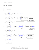
9-15. DCS Transmitter
U101
pin12,13,28,29
>=2.8V
Yes
Resolder U101
Check
UCP200
END
No
No
No
No
No
No
No
No
No
Yes
Yes
Yes
Yes
Yes
Yes
Yes
Yes
Check & Resolder RFLO
signal, RF13MHz,
RF PSU Part
Check +VBAT or PAM
control signal
Resolder or Change
Pam100
Check Pam100
+VBATT(pin17)
Yes
U101
pin 4,5,6,7
>= 1V
Resolder
R103
Resolder
L112, C117
Check ANT Switch
control circuit
Change or Resolder
L112,C117,C118
PAM100
pin3
<= -11dBm
PAM100
pin3
<=
-15dB
PAM100
pin15
>= 18dBm
F100
pin3
>= 18dBm
Check F100
pin9
= H (2.6V),
pin11
=L
TX ON (5Level)
Resolder
CN100,C104
F100
Pin7
>= 20dBm