Seagate ST19171WC Product Manual - Page 45
Installation
 |
View all Seagate ST19171WC manuals
Add to My Manuals
Save this manual to your list of manuals |
Page 45 highlights
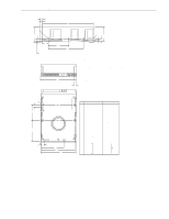
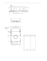
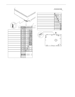
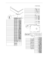
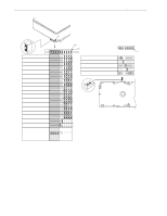
Barracuda 9 Product Manual, Rev. C 35 8.0 Installation The first thing to do when installing a drive is to set the drive ID (select) on the SCSI bus and set up certain operating options. This is usually done by installing small shorting jumpers on the pins of connectors J2 and J6 on the PCB (or J1-Auxiliary on the "W" and "WD" models), or via the drive to host I/O signals on "WC" and "DC" models. Some users connect cables to J6 or J1-Auxiliary and perform the set-up using remote switches. If your system is "SCAM" (SCSI Configured Auto Magically) compliant, the system assigns the drive ID over the interface, so there is no need to be concerned about drive ID. Setting the drive ID jumpers doesn't hurt anything, but is not necessary. If your system is not "SCAM" compliant, you do need to set the drive ID using the ID jumpers. Configure drive options For option jumper locations and definitions refer to Figures 9, 10, and 11. Drive default mode parameters are not normally needed for installation. Refer to Section 9.3.2 for default mode parameters if they are needed. • Ensure that the SCSI ID of the drive is not the same as the host adapter. Most host adapters use SCSI ID 7. ID 7 is the highest priority on both 8 and 16 bit data buses. • If multiple devices are on the bus, set the drive SCSI ID to one that is not presently used by other devices on the bus. • If the drive is the only device on the bus, attach it to the end of the SCSI bus cable. Permanently installed terminators must be enabled on the drive for "N" and "W" models using jumper plug TE if termination is not provided by the host equipment. On "WC," "WD," and "DC" models, external terminators must be provided by the user, systems integrator or host equipment manufacturer. • If the drive is attached to a bus that contains other devices and the new drive is not attached to the end of the bus, the Terminator Enable jumper (TE) should be removed from the new drive. Note. For additional information about terminator requirements, refer to Sections 9.8 and 9.9. • Set all appropriate option jumpers for desired operation prior to power on. If jumpers are changed after power has been applied, recycle the drive power to make the new settings effective. • Installation instructions are provided by host system documentation or with any additionally purchased drive installation software. If necessary, see Section 10.0 for Seagate support services telephone numbers. • Do not remove the manufacturer's installed labels from the drive and do not cover with additional labels, as the manufacturer labels contain information required when servicing the product. Formatting • It is not necessary to low level format this drive. The drive is shipped from the factory low level formatted in 512-byte sectors. • Reformat the drive if a different spare sector allocation scheme is selected. • High level format the drive involves assigning one or more partitions or logical drives to the drive volume. Follow the instructions in the system manuals for the system into which the drive is to be installed. • Systems that have Windows 95 Operating System version 950B (this has FAT32) or later do not need to par- tition the drive. 8.1 Drive ID/option select header Figures 9, 10, and 11 show views of the drive ID select and option select jumper connectors. Figure 10 shows a rear view of model drives for the purpose of showing J1-auxiliary of the drive. Both J1-auxiliary and J6 have pins for selecting drive ID and for connecting the remote LED cable. Only one or the other should be used, although using both at the same time would not damage the drive. The notes following the figures describe the functions of the various jumper positions on the connectors J2, J1-Auxiliary and J6. Suggested part number for the jumpers used on J2 is Molex 52747-0211(Seagate P/N 70935865). A bag with the two jumper plug types is shipped with the standard OEM drives.
-
 1
1 -
2
-
3
-
4
-
5
-
6
-
7
-
8
-
9
-
10
-
11
-
12
-
13
-
14
-
15
-
16
-
17
-
18
-
19
-
20
-
21
-
22
-
23
-
24
-
25
-
26
-
27
-
28
-
29
-
30
-
31
-
32
-
33
-
34
-
35
-
36
-
37
-
38
-
39
-
 40
40 -
 41
41 -
 42
42 -
 43
43 -
 44
44 -
 45
45 -
 46
46 -
 47
47 -
 48
48 -
 49
49 -
 50
50 -
51
-
52
-
53
-
54
-
55
-
56
-
57
-
58
-
59
-
60
-
61
-
62
-
63
-
64
-
65
-
66
-
67
-
68
-
69
-
70
-
71
-
72
-
73
-
74
-
75
-
76
-
77
-
78
-
79
-
80
-
81
-
82
-
83
-
84
-
85
-
86
-
87
-
88
-
89
-
90
-
91
-
92
-
93
-
94
 |
 |