Seagate ST19171WC Product Manual - Page 67
Mating connectors for ST19171WC and ST19171DC models
 |
View all Seagate ST19171WC manuals
Add to My Manuals
Save this manual to your list of manuals |
Page 67 highlights
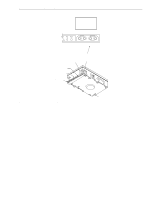
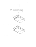
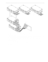
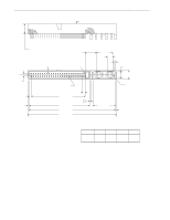
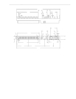
Barracuda 9 Product Manual, Rev. C 57 9.6.4 Mating connectors Part numbers for connectors that mate with the various Barracuda 9 I/O connectors are given in the sections following. 9.6.4.1 Mating connectors for ST19171N model Use a non-shielded 50-conductor cable connector consisting of two rows of 25 female contacts with adjacent centers 100 mils apart. Recommended mating flat cable connector part numbers are: 3M-3425-7000 3M-3425-7050 Berg-66900-290 W/O Strain Relief, No Center Key With Strain Relief, No Center Key With Strain Relief, With Center Key Closed-end (for cable ends) [1] 3M-3425-6000 3M-3425-6050 Berg-66900-250 W/O Strain Relief, No Center Key With Strain Relief, No Center Key With Strain Relief, With Center Key Open-end (in daisy-chain) [1] [1] See Figure 16. The drive device connector is a non-shielded 50-conductor connector consisting of two rows of 25 male pins with adjacent pins 100 mils apart. The connector is keyed (see Figure 17). Mating panel mount connector: 3M-CHE-2050-J01A10-KLE. 9.6.4.2 Mating connectors for ST19171W and ST19171WD models Use a non-shielded 68-conductor cable connector consisting of two rows of 34 male contacts with adjacent contacts 0.050 inch (1.27 mm) apart. Recommended mating wide connector part numbers are: Amp Model 786096-7 Female, 68-pin, panel mount Amp Model 786090-7 Female, 68-pin, cable mount Amp Model 749925-5 (50 mil conductor centers, 28 or 30 AWG wire) Use two, 34 conductor, 50 mil center flat cable with this connector. This type connector can only be used on cable ends. [1] Amp Model 88-5870-294-5 W/O Strain Relief (25 mil conductor centers, 30 AWG wire). Use either on cable ends or in cable middle section for daisy-chain installations. [1] Amp Model 1-480420-0 Power connector 4 circuit housing Berg 69307-012 12-position, 2 x 6, 2 mm receptacle housing [1] See Figure 16. The drive device connector is a non-shielded 68-conductor connector consisting of two rows of 34 female pins with adjacent pins 50 mils apart. The connector is keyed by means of its shape (see Figure 18). 9.6.4.3 Mating connectors for ST19171WC and ST19171DC models Use a non-shielded 80-conductor connector consisting of two rows of 40 contacts with adjacent contacts 50 (1.27 mm) mils apart. I/O connection using a cable is not recommended. The length and size of the host equipment DC power carrying conductors from the DC power source to the host equipment 80-pin disc drive interface connector should be strictly designed according to proper power transmission design concepts. Do not allow users to attach an 80-pin cable/connector, because the length of the DC power carrying conductors could not be controlled and therefore could become too long for safe power transmission to the drive. Daisy chain 80-conductor cables should especially not be allowed, since the power carrying conductors on the 80-conductor interface were not intended to support a series of drives.
-
 1
1 -
2
-
3
-
4
-
5
-
6
-
7
-
8
-
9
-
10
-
11
-
12
-
13
-
14
-
15
-
16
-
17
-
18
-
19
-
20
-
21
-
22
-
23
-
24
-
25
-
26
-
27
-
28
-
29
-
30
-
31
-
32
-
33
-
34
-
35
-
36
-
37
-
38
-
39
-
40
-
41
-
42
-
43
-
44
-
45
-
46
-
47
-
48
-
49
-
50
-
51
-
52
-
53
-
54
-
55
-
56
-
57
-
58
-
59
-
60
-
61
-
 62
62 -
 63
63 -
 64
64 -
 65
65 -
 66
66 -
 67
67 -
 68
68 -
 69
69 -
 70
70 -
 71
71 -
 72
72 -
73
-
74
-
75
-
76
-
77
-
78
-
79
-
80
-
81
-
82
-
83
-
84
-
85
-
86
-
87
-
88
-
89
-
90
-
91
-
92
-
93
-
94
 |
 |