| Section |
Page |
| Barracuda 9 Disc Drive |
1 |
| ST19171N/W/WD/WC/DC |
1 |
| Product Manual, Volume 1 |
1 |
| Barracuda 9 Disc Drive |
3 |
| ST19171N/W/WD/WC/DC |
3 |
| Product Manual, Volume 1 |
3 |
| Revision status summary sheet |
5 |
| Contents |
7 |
| 1.0 Scope 1 |
7 |
| 2.0 Applicable standards and reference documentati... |
7 |
| 2.1 Standards 3 |
7 |
| 2.1.1 Electromagnetic compatibility 3 |
7 |
| 2.1.2 Electromagnetic susceptibility 3 |
7 |
| 2.2 Electromagnetic compliance 3 |
7 |
| 2.3 Reference documents 4 |
7 |
| 3.0 General description 5 |
7 |
| 3.1 Standard features 6 |
7 |
| 3.2 Media characteristics 7 |
7 |
| 3.3 Performance 7 |
7 |
| 3.4 Reliability 7 |
7 |
| 3.5 Unformatted and formatted capacities 7 |
7 |
| 3.6 Programmable drive capacity 7 |
7 |
| 3.7 Factory installed accessories 7 |
7 |
| 3.8 Options (factory installed) 8 |
7 |
| 3.9 Accessories (user installed) 8 |
7 |
| 4.0 Performance characteristics 9 |
7 |
| 4.1 Internal drive characteristics (transparent to... |
7 |
| 4.2 SCSI seek performance characteristics (visible... |
7 |
| 4.2.1 Access time 9 |
7 |
| 4.2.2 Format command execution time 9 |
7 |
| 4.2.3 General performance characteristics 9 |
7 |
| 4.3 Start/stop time 11 |
7 |
| 4.4 Prefetch/multi-segmented cache control 11 |
7 |
| 4.5 Cache operation 11 |
7 |
| 4.5.1 Caching write data 12 |
7 |
| 4.5.2 Prefetch operation 12 |
7 |
| 5.0 Reliability specifications 15 |
7 |
| 5.1 Error rates 15 |
7 |
| 5.1.1 Environmental interference 15 |
7 |
| 5.1.2 Read errors 15 |
7 |
| 5.1.3 Write errors 15 |
7 |
| 5.1.4 Seek errors 16 |
7 |
| 5.2 Reliability and service 16 |
7 |
| 5.2.1 Mean time between failure 16 |
7 |
| 5.2.2 Preventive maintenance 16 |
7 |
| 5.2.3 Service life 16 |
7 |
| 5.2.4 Service philosophy 16 |
7 |
| 5.2.5 Service tools 16 |
7 |
| 5.2.6 Hot plugging Barracuda 9 disc drives 17 |
7 |
| 5.2.7 S.M.A.R.T. 17 |
7 |
| 5.2.8 Product warranty 18 |
7 |
| 6.0 Physical/electrical specifications 21 |
7 |
| 6.1 AC power requirements 21 |
7 |
| 6.2 DC power requirements 21 |
7 |
| 6.2.1 Conducted noise immunity 22 |
7 |
| 6.2.2 Power sequencing 22 |
7 |
| 6.2.3 12 V current profile 22 |
7 |
| 6.3 Power dissipation 23 |
7 |
| 6.4 Environmental limits 23 |
7 |
| 6.4.1 Temperature 23 |
7 |
| 6.4.2 Relative humidity 27 |
7 |
| 6.4.3 Effective altitude (sea level) 27 |
8 |
| 6.4.4 Shock and vibration 27 |
8 |
| 6.4.5 Air cleanliness 29 |
8 |
| 6.4.6 Acoustics 29 |
8 |
| 6.4.7 Electromagnetic susceptibility 29 |
8 |
| 6.5 Mechanical specifications 30 |
8 |
| 7.0 Defect and error management 33 |
8 |
| 7.1 Drive internal defects 33 |
8 |
| 7.2 Drive error recovery procedures 33 |
8 |
| 7.3 SCSI systems errors 34 |
8 |
| 8.0 Installation 35 |
8 |
| 8.1 Drive ID/option select header 35 |
8 |
| 8.1.1 Notes for Figures 9, 10, and 11 39 |
8 |
| 8.1.2 Function description 40 |
8 |
| 8.2 Drive orientation 41 |
8 |
| 8.3 Cooling 41 |
8 |
| 8.3.1 Air flow 41 |
8 |
| 8.4 Drive mounting 42 |
8 |
| 8.5 Grounding 42 |
8 |
| 9.0 Interface requirements 43 |
8 |
| 9.1 General description 43 |
8 |
| 9.2 SCSI interface messages supported 43 |
8 |
| 9.3 SCSI interface commands supported 44 |
8 |
| 9.3.1 Inquiry data 47 |
8 |
| 9.3.2 Mode Sense data 47 |
8 |
| 9.4 SCSI bus conditions and miscellaneous features... |
8 |
| 9.5 Synchronous data transfer 52 |
8 |
| 9.5.1 Synchronous data transfer periods supported ... |
8 |
| 9.5.2 REQ/ACK offset 52 |
8 |
| 9.6 Physical interface 52 |
8 |
| 9.6.1 DC cable and connector 52 |
8 |
| 9.6.2 SCSI interface physical description 55 |
8 |
| 9.6.3 SCSI interface cable requirements 55 |
8 |
| 9.6.4 Mating connectors 57 |
8 |
| 9.7 Electrical description 69 |
8 |
| 9.7.1 Single-ended drivers/receivers 69 |
8 |
| 9.7.2 Differential drivers/receivers 70 |
8 |
| 9.8 Terminator requirements 72 |
8 |
| 9.9 Terminator power 72 |
8 |
| 9.10 Disc drive SCSI timing 73 |
8 |
| 10.0 Seagate technical support services 75 |
8 |
| List of Figures |
9 |
| Figure 1. Barracuda 9 disc drive (ST19171N drive s... |
9 |
| Figure 2. Barracuda 9 family drive 6 |
9 |
| Figure 3. Typical Barracuda 9 drive +5 V and +12 V... |
9 |
| Figure 4a. Location of PCB components listed in Ta... |
9 |
| Figure 4b. Location of PCB components listed in Ta... |
9 |
| Figure 5. Recommended mounting 28 |
9 |
| Figure 6. Mounting configuration dimensions for “N... |
9 |
| Figure 7. Mounting configuration dimensions for “W... |
9 |
| Figure 8. Mounting configuration dimensions for “W... |
9 |
| Figure 9. ST19171N option select jumper connectors... |
9 |
| Figure 10. ST19171W/WD option select jumper connec... |
9 |
| Figure 11. ST19171WC/DC option select jumper conne... |
9 |
| Figure 12. Suggested air flow 41 |
9 |
| Figure 13. Physical interface for “N” model drives... |
9 |
| Figure 14. Physical interface for “W” and “WD” mod... |
9 |
| Figure 15. Physical interface for “WC” and “DC” mo... |
9 |
| Figure 16. SCSI daisy-chain interface cabling 59 |
9 |
| Figure 17. Non-shielded 50-pin SCSI device connect... |
9 |
| Figure 18. Non-shielded 68-pin SCSI device connect... |
9 |
| Figure 19. Non-shielded 80-pin SCSI connector, use... |
9 |
| Figure 20. Single-ended transmitters and receivers... |
9 |
| Figure 21. Typical differential I/O line transmitt... |
9 |
| 1.0 Scope |
11 |
| Figure 1. Barracuda 9 disc drive (ST19171N drive s... |
11 |
| 2.0 Applicable standards and reference documentati... |
13 |
| 2.1 Standards |
13 |
| 2.1.1 Electromagnetic compatibility |
13 |
| 2.1.2 Electromagnetic susceptibility |
13 |
| 2.2 Electromagnetic compliance |
13 |
| Electromagnetic compliance for the European Union |
13 |
| Australian C-Tick |
14 |
| 2.3 Reference documents |
14 |
| 3.0 General description |
15 |
| Table 1: Drive model number vs. differentiating fe... |
15 |
| Figure 2. Barracuda 9 family drive |
16 |
| 3.1 Standard features |
16 |
| 3.2 Media characteristics |
17 |
| 3.3 Performance |
17 |
| Note. |
17 |
| [1] Some host adapter companies support the term “... |
17 |
| 3.4 Reliability |
17 |
| 3.5 Unformatted and formatted capacities |
17 |
| Notes. |
17 |
| [1] Standard OEM models are formatted to have 512-... |
17 |
| [2] The number of data tracks per sparing zone and... |
17 |
| 3.6 Programmable drive capacity |
17 |
| 3.7 Factory installed accessories |
17 |
| 3.8 Options (factory installed) |
18 |
| 3.9 Accessories (user installed) |
18 |
| 4.0 Performance characteristics |
19 |
| 4.1 Internal drive characteristics (transparent to... |
19 |
| [1] Rounded off values |
19 |
| 4.2 SCSI seek performance characteristics (visible... |
19 |
| 4.2.1 Access time [7] |
19 |
| 4.2.2 Format command execution time |
19 |
| 4.2.3 General performance characteristics |
19 |
| Notes for Sections 4.2. |
20 |
| [1] Execution time is measured from receipt of the... |
20 |
| [2] Typical access times are measured under nomina... |
20 |
| [3] Assumes no errors and no sector reallocations.... |
20 |
| [4] Rate measured from the start of the first sect... |
20 |
| [5] Assumes system ability to support the rates li... |
20 |
| [6] Assumes system ability to support the rates li... |
20 |
| [7] Access time = controller overhead + average se... |
20 |
| 4.3 Start/stop time |
21 |
| 4.4 Prefetch/multi-segmented cache control |
21 |
| 4.5 Cache operation |
21 |
| 1. Drive transfers to the initiator the first logi... |
21 |
| 2. When a requested logical block is reached that ... |
21 |
| 3. The drive prefetches additional logical blocks ... |
21 |
| 1. The drive fetches the requested logical blocks ... |
22 |
| 2. The drive prefetches additional logical blocks ... |
22 |
| 4.5.1 Caching write data |
22 |
| 4.5.2 Prefetch operation |
22 |
| 5.0 Reliability specifications |
25 |
| Note. |
25 |
| [1] Error rate specified with automatic retries an... |
25 |
| 5.1 Error rates |
25 |
| 5.1.1 Environmental interference |
25 |
| 5.1.2 Read errors |
25 |
| 5.1.3 Write errors |
25 |
| 5.1.4 Seek errors |
26 |
| 5.2 Reliability and service |
26 |
| 5.2.1 Mean time between failure |
26 |
| 5.2.2 Preventive maintenance |
26 |
| 5.2.3 Service life |
26 |
| 5.2.4 Service philosophy |
26 |
| 5.2.5 Service tools |
26 |
| 5.2.6 Hot plugging Barracuda 9 disc drives |
27 |
| 1. Configure the drive with no connection between ... |
27 |
| 2. Ensure that all SCSI devices on the bus have re... |
27 |
| 3. Eliminate all I/O processes for the drive. |
27 |
| 4. Wait until the drive motor and discs have come ... |
27 |
| 5. Insert or remove the drive after meeting the fo... |
27 |
| a. If you are inserting the drive, connect its pow... |
27 |
| b. If you are removing the device, maintain its po... |
27 |
| c. You may simultaneously switch the power to the ... |
27 |
| d. Ensure that the drive carrier discharges all st... |
27 |
| 5.2.7 S.M.A.R.T. |
27 |
| Controlling S.M.A.R.T. |
27 |
| Performance impact |
28 |
| Reporting control |
28 |
| Determining rate |
28 |
| Predictive failures |
28 |
| 5.2.8 Product warranty |
28 |
| Shipping |
28 |
| Product repair and return information |
29 |
| 6.0 Physical/electrical specifications |
31 |
| 6.1 AC power requirements |
31 |
| 6.2 DC power requirements |
31 |
| Table 2: DC power requirements |
31 |
| [1] Measured with average reading DC ammeter. Inst... |
31 |
| [2] A –10% droop is permissible during initial sta... |
31 |
| [3] See +12V current profile in Figure 3. |
31 |
| [4] This condition occurs when the Motor Start Opt... |
31 |
| [5] See Section 6.2.1 “Conducted Noise Immunity.” ... |
31 |
| [6] At power-up, the motor current regulator limit... |
31 |
| [7] Operating condition is defined as a third-stro... |
31 |
| [8] No terminator power. See Section 9.9. |
31 |
| [9] Track following at track 0. |
32 |
| [10] Seeking is defined as a third-stroke seek at ... |
32 |
| [11] Read track is defined as repeat reads of trac... |
32 |
| 1. Minimum current loading for each supply voltage... |
32 |
| 2. The +5 and +12 volt supplies shall employ separ... |
32 |
| 3. Where power is provided to multiple drives from... |
32 |
| 6.2.1 Conducted noise immunity |
32 |
| 6.2.2 Power sequencing |
32 |
| 6.2.3 12 V current profile |
32 |
| Figure 3. Typical Barracuda 9 drive +5 V and +12 V... |
33 |
| 6.3 Power dissipation |
33 |
| ST19171N/W/WC |
33 |
| ST19171WD/DC |
33 |
| 6.4 Environmental limits |
33 |
| 6.4.1 Temperature |
33 |
| a. Operating |
33 |
| Table 3: PCB and HDA temperatures |
34 |
| Notes. |
34 |
| [1] Section 8.3.1 describes the air-flow patterns ... |
34 |
| [2] The temperatures in Column 1 are calculated an... |
34 |
| [3] Measure HDA temperature at point labeled “HDA ... |
34 |
| [4] PCB mounted integrated circuit case. |
34 |
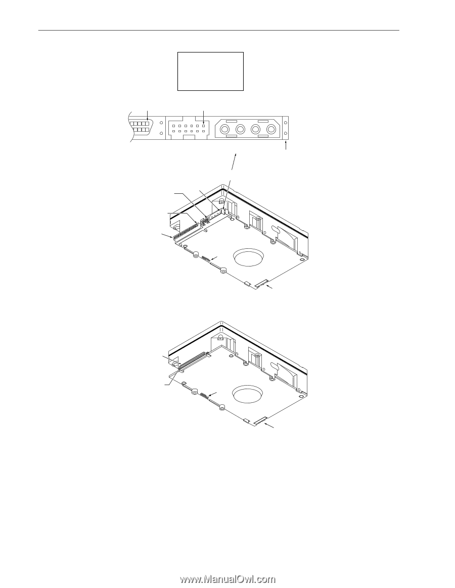
| Figure 4a. Location of PCB components listed in Ta... |
35 |
| Figure 4b. Location of PCB components listed in Ta... |
36 |
| b. Non-operating |
37 |
| 6.4.2 Relative humidity |
37 |
| a. Operating |
37 |
| b. Non-operating/transit |
37 |
| 6.4.3 Effective altitude (sea level) |
37 |
| a. Operating |
37 |
| b. Non-operating |
37 |
| 6.4.4 Shock and vibration |
37 |
| 6.4.4.1 Shock |
37 |
| a. Operating—normal |
37 |
| b. Operating—abnormal |
37 |
| c. Non-operating |
37 |
| d. Packaged |
38 |
| Figure 5. Recommended mounting |
38 |
| 6.4.4.2 Vibration |
38 |
| a. Operating—normal |
38 |
| b. Operating—abnormal |
38 |
| c. Non-operating |
39 |
| 6.4.5 Air cleanliness |
39 |
| 6.4.6 Acoustics |
39 |
| 6.4.7 Electromagnetic susceptibility |
39 |
| 6.5 Mechanical specifications |
40 |
| Figure 6. Mounting configuration dimensions for “N... |
40 |
| Figure 7. Mounting configuration dimensions for “W... |
41 |
| Figure 8. Mounting configuration dimensions for “W... |
42 |
| 7.0 Defect and error management |
43 |
| 7.1 Drive internal defects |
43 |
| 7.2 Drive error recovery procedures |
43 |
| Table 4: Read and write retry count maximum recove... |
44 |
| [1] Setting these retry counts to a value below th... |
44 |
| 7.3 SCSI systems errors |
44 |
| 8.0 Installation |
45 |
| Configure drive options |
45 |
| Formatting |
45 |
| 8.1 Drive ID/option select header |
45 |
| Figure 9. ST19171N option select jumper connectors... |
46 |
| Figure 10. ST19171W/WD option select jumper connec... |
47 |
| Figure 11. ST19171WC/DC option select jumper conne... |
48 |
| 8.1.1 Notes for Figures 9, 10, and 11 |
49 |
| [1] Notes explaining the functions of the various ... |
49 |
| [2] The PCB on “N,” “WC,” and “DC” model drives do... |
49 |
| [3] Reserved useage. Do not install any jumpers. |
49 |
| [4] Table 5 summarizes the configuration selection... |
49 |
| [5] These signals are also on 80 pin J1. See Table... |
49 |
| [6] Voltage supplied by the drive. |
49 |
| Table 5: Drive configuration selections summary |
49 |
| Notes for Table 5 [�]: |
49 |
| [a] Use either J6 or J1-Aux, but not both. |
49 |
| [b] I/O connector J1 plugs directly into host. No ... |
49 |
| [c] The host can drive a remotely located Drive Ac... |
49 |
| [d] Use either J1 or J6, but not both. |
49 |
| [e] The drive reads the ID (asserted low) from J1-... |
49 |
| [f] The host selects drive ID through J1. |
49 |
| 8.1.2 Function description |
50 |
| 8.2 Drive orientation |
51 |
| 8.3 Cooling |
51 |
| 8.3.1 Air flow |
51 |
| Figure 12. Suggested air flow |
51 |
| 8.4 Drive mounting |
52 |
| 8.5 Grounding |
52 |
| 9.0 Interface requirements |
53 |
| 9.1 General description |
53 |
| 9.2 SCSI interface messages supported |
53 |
| Table 6: SCSI messages supported by Barracuda 9 fa... |
53 |
| Notes. |
53 |
| [1] Extended message (refer to the SCSI Interface ... |
53 |
| [2] Not applicable to “N” models. |
53 |
| 9.3 SCSI interface commands supported |
54 |
| Table 7: Commands supported by Barracuda 9 family ... |
54 |
| [1] The drive can format to any even number of byt... |
56 |
| [2] Table 9 shows how individual bits are set that... |
56 |
| [3] Warning: A power loss during flash programming... |
56 |
| 9.3.1 Inquiry data |
57 |
| Table 8: Barracuda 9 family drive Standard Inquiry... |
57 |
| Notes. |
57 |
| 9.3.1.1 Inquiry Vital Product Data pages |
57 |
| 9.3.2 Mode Sense data |
57 |
| Definitions: |
59 |
| Table 9: Mode Sense data, ST19171 default values (... |
59 |
| [1] Though byte 12, bit 7 is shown as changeable, ... |
60 |
| [2] Default and saved values for page 10h, bytes 6... |
60 |
| 9.4 SCSI bus conditions and miscellaneous features... |
61 |
| Table 10: SCSI bus conditions and other miscellane... |
61 |
| 9.5 Synchronous data transfer |
62 |
| 9.5.1 Synchronous data transfer periods supported |
62 |
| Table 11: Synchronous data transfer periods suppor... |
62 |
| [1] Fast-20 (Ultra SCSI) transfer rates. |
62 |
| 9.5.2 REQ/ACK offset |
62 |
| 9.6 Physical interface |
62 |
| 9.6.1 DC cable and connector |
62 |
| Figure 13. Physical interface for “N” model drives... |
63 |
| Figure 14. Physical interface for “W” and “WD” mod... |
64 |
| Figure 15. Physical interface for “WC” and “DC” mo... |
64 |
| 9.6.2 SCSI interface physical description |
65 |
| 9.6.3 SCSI interface cable requirements |
65 |
| 9.6.3.1 Single-ended I/O circuits (“N,” “W,” and “... |
66 |
| Table 12: Cable characteristics for single-ended c... |
66 |
| Notes: |
66 |
| [1] The spacing of devices on the mainline SCSI bu... |
66 |
| 9.6.3.2 Differential I/O circuits (“WD” and “DC” m... |
66 |
| 9.6.4 Mating connectors |
67 |
| 9.6.4.1 Mating connectors for ST19171N model |
67 |
| [1] See Figure 16. |
67 |
| 9.6.4.2 Mating connectors for ST19171W and ST19171... |
67 |
| [1] See Figure 16. |
67 |
| 9.6.4.3 Mating connectors for ST19171WC and ST1917... |
67 |
| [1] Closed-end type 50-pin connector used. Install... |
69 |
| [2] Open-end type (in-line application) connector ... |
69 |
| [3] Host need not be on the end of the daisy chain... |
69 |
| [4] Total interface cable length must not exceed t... |
69 |
| [5] SCSI ID7 has highest arbitration priority, ID ... |
69 |
| [6] Last drive on daisy chain. |
69 |
| [7] Open-end type 68-pin connector used. Terminato... |
69 |
| Figure 16. SCSI daisy-chain interface cabling |
69 |
| Figure 17. Non-shielded 50-pin SCSI device connect... |
70 |
| Figure 18. Non-shielded 68-pin SCSI device connect... |
71 |
| Figure 19. Non-shielded 80-pin SCSI connector, use... |
72 |
| Table 13: Single-ended signal/contact assignments ... |
73 |
| Table 14: Single-ended wide cable assignments for ... |
74 |
| Table 15: Wide differential P cable assignments (n... |
75 |
| Notes [ ]: See page following Table 17. |
75 |
| Table 16: Wide, single connector, single-ended sig... |
76 |
| Notes [ ]: See page following Table 17. |
76 |
| Table 17: Wide, single connector, differential sig... |
77 |
| Notes [ ]: See page following this Table. |
77 |
| Notes [����] for Tables 13 through 17: |
78 |
| [1] See Section 9.7.1 for detailed electrical char... |
78 |
| [2] The conductor number refers to the conductor p... |
78 |
| [3] Connector contacts are on 0.050 inch (1.27 mm)... |
78 |
| [4] Front panel LED signal; indicates drive activi... |
78 |
| [5] Asserted by host to enable Motor Start option ... |
78 |
| [6] Asserted by host to enable Delayed Motor Start... |
78 |
| [7] Binary code on A3, A2, A1, and A0 asserted by ... |
78 |
| [8] GND provides a means for differential devices ... |
78 |
| [9] Signals [4] through [7] are used in place of i... |
78 |
| [10] “NC” means no connection. |
78 |
| [11] The conductor number refers to the conductor ... |
78 |
| [12] Connector contacts are on 0.100 inch (2.54 mm... |
78 |
| [13] 8 bit devices which are connected to the 16 d... |
78 |
| 9.7 Electrical description |
79 |
| 9.7.1 Single-ended drivers/receivers |
79 |
| Transmitter characteristics |
79 |
| Receiver characteristics |
79 |
| Figure 20. Single-ended transmitters and receivers... |
79 |
| Notes. |
79 |
| [1] Part of active terminator circuits. Non-remova... |
79 |
| [2] ANSI SCSI compatible circuits. |
79 |
| [3] Total interface cable length should not exceed... |
79 |
| [4] Source of drive terminator power is an active ... |
79 |
| [5] Interface signal levels and logical sense at t... |
79 |
| 9.7.2 Differential drivers/receivers |
80 |
| Notes. |
81 |
| [1] Positive logic enables transmitter (+5 V = ass... |
81 |
| [2] Negative logic signal (0 V = asserted). |
81 |
| [3] Total interface cable length should not exceed... |
81 |
| [4] I/O line terminators. If SCSI device is a Seag... |
81 |
| [5] Arrangements for connecting terminator power t... |
81 |
| [6] SCSI I/O line (pin 21) disables I/O circuits i... |
81 |
| [7] SCSI I/O cable ground. See Tables 15 and 17. |
81 |
| Figure 21. Typical differential I/O line transmitt... |
81 |
| 9.8 Terminator requirements |
82 |
| ST19171N and ST19171W drives |
82 |
| ST19171WC and ST19171DC drives |
82 |
| ST19171WD drives |
82 |
| 9.9 Terminator power |
82 |
| ST19171N and ST19171W drives |
82 |
| 1. Drive accepts terminator power through SCSI bus... |
82 |
| 2. Drive supplies power to the SCSI bus. |
82 |
| 3. Drive provides terminator power for optional in... |
82 |
| 4. Drive provides power to its own terminators and... |
82 |
| ST19171WD drives |
82 |
| ST19171WC and ST19171DC drives |
82 |
| 9.10 Disc drive SCSI timing |
83 |
| Table 18: Disc drive SCSI timing |
83 |
| Notes. |
84 |
| [1] See the SCSI �Interface� Product� Manual, part... |
84 |
| [2] Maximum SCSI asynchronous interface transfer r... |
84 |
| [3] Synchronous Transfer Period is determined by n... |
84 |
| 10.0 Seagate technical support services |
85 |
| Index |
87 |
| Numerics |
87 |
| A |
87 |
| B |
87 |
| C |
87 |
| D |
87 |
| E |
88 |
| F |
88 |
| G |
88 |
| H |
88 |
| I |
89 |
| J |
89 |
| L |
89 |
| M |
89 |
| N |
90 |
| O |
90 |
| P |
90 |
| Q |
90 |
| R |
90 |
| S |
91 |
| T |
91 |
| U |
92 |
| V |
92 |
| W |
92 |
| X |
92 |
 1
1 59
59 60
60 61
61 62
62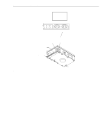 63
63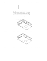 64
64 65
65 66
66 67
67 68
68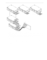 69
69