Seagate ST3660A Product Manual - Page 23
Factory-test configuration, Optional drive activity LED
 |
View all Seagate ST3660A manuals
Add to My Manuals
Save this manual to your list of manuals |
Page 23 highlights
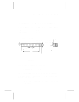
Medalist XE Family Product Manual, Rev. B 15 Slave CSEL not carried to pin 28 of this connector Master Pin 28 grounded at computer Computer Figure 4. Connecting cable-selected drives 2.4.4 Factory-test configuration Do not install jumpers on pins 5 and 6 and pins 7 and 8 at the same time. This configuration is used to test the drive at the factory. When jumpers are installed in both of these positions, the heads continuously seek back and forth across the media and the drive ignores all control signals sent by the interface. 2.5 Optional drive activity LED The drives are available with or without the external activity LED shown in Figure 3 on page 13. This option is available for users for whom the activity display through the bus is inaccessible or inconvenient. There are two LED options: • The LED is mounted directly on the printed circuit board, or • A two-pin header is mounted on the printed circuit board for a remote LED. The anode pin of the header is nearest the edge of the PCB.
-
 1
1 -
2
-
3
-
4
-
5
-
6
-
7
-
8
-
9
-
10
-
11
-
12
-
13
-
14
-
15
-
16
-
17
-
 18
18 -
 19
19 -
 20
20 -
 21
21 -
 22
22 -
 23
23 -
 24
24 -
 25
25 -
 26
26 -
 27
27 -
 28
28 -
29
-
30
-
31
-
32
-
33
-
34
-
35
-
36
-
37
-
38
-
39
-
40
 |
 |