Seagate ST3660A Product Manual - Page 27
ATA interface
 |
View all Seagate ST3660A manuals
Add to My Manuals
Save this manual to your list of manuals |
Page 27 highlights
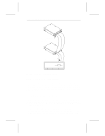
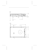
Medalist XE Family Product Manual, Rev. B 19 3.0 ATA interface This section discusses commands and modes whose implementation is unique for these drives. For a general discussion of the Seagate ATA interface, refer to the Seagate ATA Interface Reference Manual, publication number 36111-xxx. Onboard diagnostics, ECC performance test and supported BIOS are also discussed. 3.1 ATA interface connector pin assignments The drive is connected to the computer through the 40-pin interface connector shown in Figure 3 on page 13. The pin assignments for the interface are shown in Figure 7 on page 20. For a complete description of each pin, see the Seagate ATA Interface Reference Manual. Note. This text uses the following conventions: • Signal names are in upper case. • Signal names followed by a minus sign (-) indicate that the signal is active low. Otherwise, the signal is active high. Note. The drives do not use the SPSYNC- signal. 3.2 Bus signal levels Signals that the drive sends have the following output characteristics measured at the drive connector. Logic low Logic high 0 to 0.4V 2.5 to 5.25V Signals that the drive receives must have the following input characteristics measured at the drive connector. Logic low Logic high 0 to 0.8V 2.0 to 5.25V
-
 1
1 -
2
-
3
-
4
-
5
-
6
-
7
-
8
-
9
-
10
-
11
-
12
-
13
-
14
-
15
-
16
-
17
-
18
-
19
-
20
-
21
-
 22
22 -
 23
23 -
 24
24 -
 25
25 -
 26
26 -
 27
27 -
 28
28 -
 29
29 -
 30
30 -
 31
31 -
 32
32 -
33
-
34
-
35
-
36
-
37
-
38
-
39
-
40
 |
 |