Seagate ST800FM0012 Pulsar Serial ATA Product Manual - Page 27
Drive mounting
 |
View all Seagate ST800FM0012 manuals
Add to My Manuals
Save this manual to your list of manuals |
Page 27 highlights
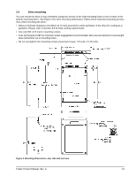
3.4 Drive mounting You can mount the drive in any orientation using four screws in the side-mounting holes or four screws in the bottom-mounting holes. See Figure 3 for drive mounting dimensions. Follow these important mounting precautions when mounting the drive: • Allow a minimum clearance of 0.030 in (0.76 mm) around the entire perimeter of the drive for cooling as a guideline. Please refer to Section 3.5 for final cooling requirements. • Use only M3 x 0.5 metric mounting screws. • Four (4) threads (0.080 in) minimum screw engagement recommended. Also ensure maximum screw length does not bottom out in mounting holes. • Do not overtighten the mounting screws (maximum torque: 4.5 in-lb, ± 0.45 in-lb). Figure 3. Mounting dimensions-top, side and end view Pulsar Product Manual, Rev. A 21
-
 1
1 -
2
-
3
-
4
-
5
-
6
-
7
-
8
-
9
-
10
-
11
-
12
-
13
-
14
-
15
-
16
-
17
-
18
-
19
-
20
-
21
-
 22
22 -
 23
23 -
 24
24 -
 25
25 -
 26
26 -
 27
27 -
 28
28 -
 29
29 -
 30
30 -
 31
31 -
 32
32 -
33
-
34
-
35
-
36
-
37
-
38
-
39
-
40
-
41
-
42
-
43
-
44
-
45
-
46
-
47
-
48
-
49
-
50
 |
 |
