Sharp KB-3300JW Installation Manual - Page 4
Power Cord Connections
 |
View all Sharp KB-3300JW manuals
Add to My Manuals
Save this manual to your list of manuals |
Page 4 highlights
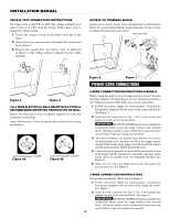
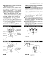
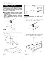
INSTALLATION MANUAL 208/240 VOLT CONNECTION INSTRUCTIONS The range can be set for 208V or 240V. Thescvreowltage settin1g80˚for your range is pre-set at 240V from the factory. Follow these steps to change the voltage setting. 1 Locate the voltage switch on the lower back side of the range. 2 Remove the screw and rotate the switch plate 180˚ as indicated in the Figure 3. 3 Reinsert the switch plate and replace screw as indicated in Figure 4. The voltage setting is indicated by the visible marking. screw 240V ACCESS TO TERMINAL BLOCK Loosen screw on rear access cover and pull down as illustrated in Figure 6 to access terminal block wiring cstoraninnerecliteiof cnla. mTop close, return to original location and secure screw. strain relief clamp 240V 208V 180˚ screw Figure 3 Figure 4 208V screw 3 & 4-WIRE ELECTRICAL WALL RECEPTACLE TYPES & RECOMMENDED MOUNTING ORIENTATION ON WALL Figure 5A illustrates 4-wire receptacle required for new and remodeled installations. Figure 5B illustrates 3-wire receptacle that is allowed for existing installations. 4-wire wall receptacle (14-50R) 4-wire wall receptacle (14-50R) Figure 5A 3-wire wall receptacle (10-50R) Figure 5B Figure 6 Figure 7 POWER CORD CONNECTIONS 4-WIRE CONNECTION INSTRUCTIONS-FIGURE 8 Before wiring the range, review the suggested power source location drawing in Figure 2. If connecting to a 4-wire electrical system for a new branch-circuit or mobile home use a 4-wire connection. 1 Follow the power supply kit manufacturerʼs Installation Instructions supplied with the strain relief clamp and install. See Figure 7. 2 Insert the end connectors for line 1, line 2 and neutral and tighten securely to the terminal block. IMPORTANT DO NOT LOOSEN the factory installed nut connections which secure the range wiring to the terminal block. Electrical failure or loss of electrical connection may occur if these 3 nuts are loosened or removed. 3 You must disconnect the ground strap. Remove the factory installed ground screw and plate to release the copper ground strap from the frame of the range. Cut and discard the copper ground strap and plate. KEEP the ground screw. 4 Connect the green ground wire lead with the eyelet to the frame of the range with the ground screw using the same hole in the frame where the ground screw was originally installed. See Figure 8. 5 Make sure all screws are tightened securely and replace the rear access cover. See Figure 6. 3-wire wall receptacle (10-50R) 3-WIRE CONNECTION INSTRUCTIONS For existing installations ONLY, refer to Figure 9. 1 Follow the power supply kit manufacturerʼs Installation Instructions supplied with the strain relief clamp and install. See Figure 7. 2 Insert the end connectors for line 1, line 2 and neutral and tighten securely to the terminal block. See Figure 7. IMPORTANT DO NOT LOOSEN the factory installed nut connections which secure the range wiring to the terminal block. Electrical failure or loss of electrical connection may occur if these 3 nuts are loosened or removed. 4
-
 1
1 -
 2
2 -
 3
3 -
 4
4 -
 5
5 -
 6
6 -
 7
7 -
 8
8
 |
 |
