Sharp KB-3300JW Installation Manual - Page 6
Adjustable Backsplash
 |
View all Sharp KB-3300JW manuals
Add to My Manuals
Save this manual to your list of manuals |
Page 6 highlights
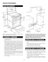
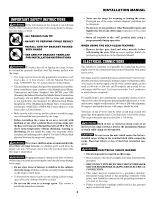
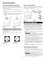
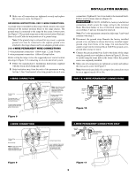
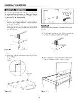
INSTALLATION MANUAL ADJUSTABLE BACKSPLASH The range backsplash is adjustable so that you can customize it for your particular kitchen situation. The height can be adjusted from the low position (6-inches high) to the highest position (12-inches high) in one inch increments. 1 Remove screw from the cooktop back frame end cap on both sides and screw from range back cover on both sides, as shown in Figure 12. Note: Set screws to the side to use for mounting the backsplash. The two back plate screws must be placed back into the back cover. Rubber Gasket End cap Parts Supplied 4 Screws 1 Backsplash 1 Rubber Gasket IMPORTANT This backsplash must be installed before the range is moved into place. 3 Carefully pull each end cap back slightly-no more than 1/8-inch-to facilitate installing the backsplash. Parts Supplied Back cover Figure 12 Back cover1scBraewcksplash 4 Screws Cooktop Back Frame 1 Rubber Gasket No more than 1/8" 2 Slide rubber gasket on back edge of cooktop back frame as shown in Figure 13. Rubber Gasket Cooktop Back Frame End Caps 4 Slide backsplash in to desired height. Secure into position with screws supplied and those removed in step 1. Figure 13 Cooktop Back Frame Cooktop Back Frame End Caps Figure 14 6
-
 1
1 -
 2
2 -
 3
3 -
 4
4 -
 5
5 -
 6
6 -
 7
7 -
 8
8
 |
 |
