Sharp LC-26SB14U Service Manual - Page 12
Refer to Fig. 2-6., Refer to Fig. 2-7., Refer to Fig. 2-8., INSTALLATION, Refer to Fig. 2-5.
 |
View all Sharp LC-26SB14U manuals
Add to My Manuals
Save this manual to your list of manuals |
Page 12 highlights
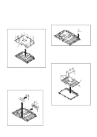
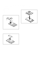
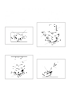
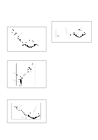
DISASSEMBLY INSTRUCTIONS INSTALLATION 1. Take care of the polarity of new IC and then install the new IC fitting on the printed circuit pattern. Then solder each lead on the diagonal positions of IC temporarily. (Refer to Fig. 2-5.) 4. When bridge-soldering between terminals and/or the soldering amount are not enough, resolder using a Thintip Soldering Iron. (Refer to Fig. 2-8.) Thin-tip Soldering Iron IC Soldering Iron Solder temporarily Solder temporarily Fig. 2-5 2. Supply the solder from the upper position of IC leads sliding to the lower position of the IC leads. (Refer to Fig. 2-6.) Solder Soldering Iron IC Supply soldering from upper position to lower position Fig. 2-6 3. Absorb the solder left on the lead using the Braided Shield Wire. (Refer to Fig. 2-7.) NOTE Do not absorb the solder to excess. Soldering Iron IC Fig. 2-8 5. Finally, confirm the soldering status on four sides of the IC using a magnifying glass. Confirm that no abnormality is found on the soldering position and installation position of the parts around the IC. If some abnormality is found, correct by resoldering. NOTE When the IC leads are bent during soldering and/or repairing, do not repair the bending of leads. If the bending of leads are repaired, the pattern may be damaged. So, always be sure to replace the IC in this case. Braided Shield Wire Fig. 2-7 B2-2
-
 1
1 -
2
-
3
-
4
-
5
-
6
-
 7
7 -
 8
8 -
 9
9 -
 10
10 -
 11
11 -
 12
12 -
 13
13 -
 14
14 -
 15
15 -
 16
16 -
 17
17 -
18
-
19
-
20
-
21
-
22
-
23
-
24
-
25
-
26
-
27
-
28
-
29
-
30
-
31
-
32
-
33
-
34
-
35
-
36
-
37
-
38
-
39
-
40
-
41
-
42
-
43
-
44
-
45
-
46
-
47
-
48
-
49
-
50
-
51
-
52
-
53
-
54
-
55
-
56
-
57
-
58
-
59
-
60
-
61
-
62
 |
 |
