Sharp LC26SB24U Operation Manual - Page 11
Part names - parts for
 |
UPC - 074000371101
View all Sharp LC26SB24U manuals
Add to My Manuals
Save this manual to your list of manuals |
Page 11 highlights
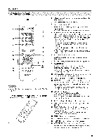
Part names L¸ - ol I I Remote control sensor POWER indicator • The buttons on the main unit have the same functions as the same buttons on the remote control. Fundamentally, this operation manual provides a description based on operation using the remote control. COAXIAL DIGITAL AUDIO OUTPUT terminal INPUT 5 terminals INPUT 4 terminals INPUT 6 terminals -INPUT 1 terminals _ INPUT 23 teerrmmiinnaalsls INPUT • The illustrations in this operation manual are for explanation purposes and may vary slightly from the actual operations. _=10
-
 1
1 -
2
-
3
-
4
-
5
-
 6
6 -
 7
7 -
 8
8 -
 9
9 -
 10
10 -
 11
11 -
 12
12 -
 13
13 -
 14
14 -
 15
15 -
 16
16 -
17
-
18
-
19
-
20
-
21
-
22
-
23
-
24
-
25
-
26
-
27
-
28
-
29
-
30
-
31
-
32
-
33
-
34
-
35
-
36
-
37
-
38
-
39
-
40
-
41
-
42
-
43
-
44
-
45
-
46
-
47
-
48
-
49
-
50
-
51
-
52
-
53
-
54
-
55
-
56
-
57
-
58
-
59
-
60
-
61
-
62
-
63
-
64
-
65
-
66
-
67
-
68
-
69
-
70
-
71
-
72
-
73
-
74
-
75
-
76
-
77
-
78
-
79
-
80
-
81
-
82
-
83
-
84
-
85
-
86
-
87
-
88
-
89
-
90
 |
 |
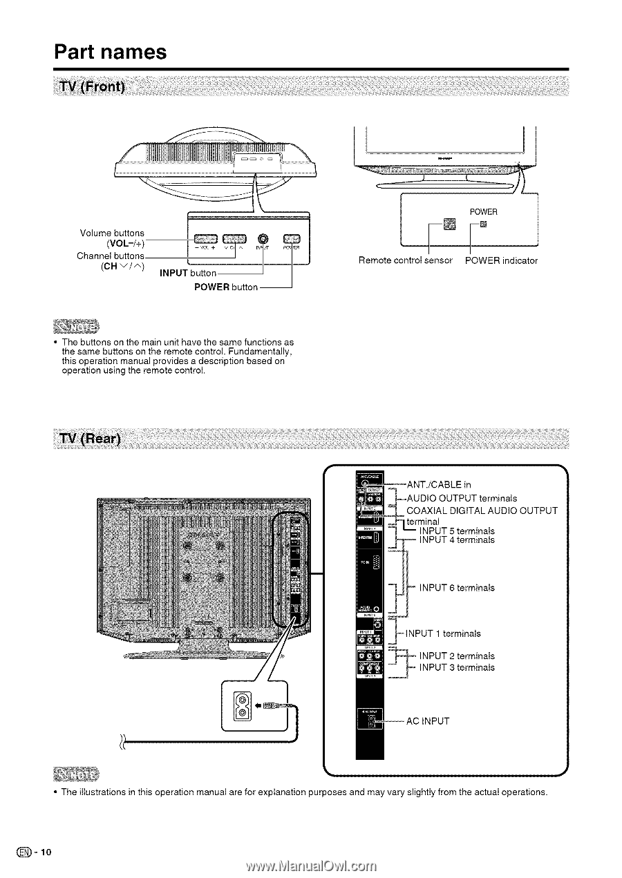
Part names
L¸
-
ol
I
I
Remote control sensor
POWER
indicator
• The buttons on the main unit have the same functions as
the same buttons on the remote control. Fundamentally,
this operation
manual provides a description
based on
operation
using the remote control.
COAXIAL
DIGITAL AUDIO OUTPUT
terminal
INPUT 5 terminals
INPUT 4 terminals
INPUT 6 terminals
-INPUT 1 terminals
_
INPUT 2 terminals
INPUT 3 terminals
INPUT
• The illustrations
in
this operation
manual are for explanation
purposes
and may vary slightly from the actual operations.
_=10