Sony BKM-21D Installation Manual - Page 32
BKM-22X SDI Input Expansion Adaptor, Functions, Using the Input and Output Connectors
 |
View all Sony BKM-21D manuals
Add to My Manuals
Save this manual to your list of manuals |
Page 32 highlights
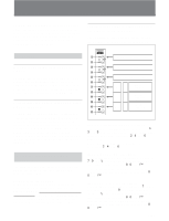
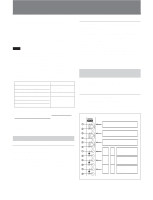
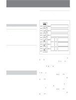
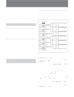
BKM-22X SDI Input Expansion Adaptor The BKM-22X SDI Input Expansion Adaptor is a video signal input adaptor for BVM-Series video monitors. When installed in an input option slot on the rear panel of the video monitor, it provides video input and output connectors for the monitor. Configuration of Input/Output Connectors and Signals that may be Input The configuration of the input and output connectors and the signals that may be input are shown below. Functions Expansion of Serial Digital Inputs The BKM-22X is not equipped with decoders, but if decoder adaptors are installed in other input option slots, you can use them to decode serial digital signals input to the BKM-22X. Expansion of analog composite or analog component inputs is also possible. Serial Digital and Analog Input and Output Signal Connectors The BKM-22X is equipped with three input and three output connectors for serial digital signals, as well as three input and three output connectors for analog signals. Using the analog signal input connectors, you can input one Y/R-Y/B-Y or one RGB signal, or three analog composite signals. The types of analog composite signals that may be input vary depending on the input adaptors installed in other input option slots (see page 20(E)). Using the Input and Output Connectors For information about installing the BKM-22X in a video monitor input option slot, see "Installing into Video Monitors" (page 21(E)). 8(E) DIGITAL ANALOG 1 IN 1 2 OUT 3 IN 2 4 OUT 5 IN 3 6 OUT 7 IN 4 8 OUT 9 IN 5 0 OUT !¡ IN 6 !™ OUT Serial digital signals Serial digital signals Serial digital signals Y G B-Y B R-Y R Analog composite signals Analog composite signals Analog composite signals Input of serial digital signals You can input serial digital signals to connectors 1, 3, and 5. You can obtain active loop-through output of those signals from connectors 2, 4, and 6, respectively. You need not attach 75-ohm terminations to connectors 2, 4, and 6. Input of analog composite signals You can input analog composite signals to connectors 7, 9, and !¡. You can obtain loop-through output of those signals from connectors 8, 0, and !™ , respectively. If you do not wish to use loop-through output, attach 75-ohm terminators to connectors 8, 0, and !™ . Input of Y/R-Y/B-Y or RGB signals You can input a Y or G signal to connector 7, an B-Y or B signal to connector 9, and a R-Y or R signal to connector !¡. You can obtain loop-through output of those signals from connectors 8, 0, and !™ , respectively. If you do not wish to use loop-through output, attach 75-ohm terminators to connectors 8, 0, and !™ .
-
 1
1 -
2
-
3
-
4
-
5
-
6
-
7
-
8
-
9
-
10
-
11
-
12
-
13
-
14
-
15
-
16
-
17
-
18
-
19
-
20
-
21
-
22
-
23
-
24
-
25
-
26
-
 27
27 -
 28
28 -
 29
29 -
 30
30 -
 31
31 -
 32
32 -
 33
33 -
 34
34 -
 35
35 -
 36
36 -
 37
37 -
38
-
39
-
40
-
41
-
42
-
43
-
44
-
45
-
46
-
47
-
48
 |
 |
