Sony CPD-110EST Operation Guide - Page 5
Identifying parts and controls
 |
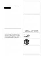
View all Sony CPD-110EST manuals
Add to My Manuals
Save this manual to your list of manuals |
Page 5 highlights
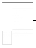
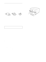
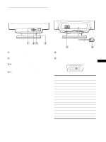
Identifying parts and controls See the pages in parentheses for further details. Front Rear MENU ENTER 1 MENU button (page 9) This button displays the MENU OSD. 2 ENTER button (page 9) This button selects the menu and adjustment items. 3 6 (contrast) +/− buttons (page 9) These buttons display the CONTRAST/BRIGHTNESS menu and function as the +/− buttons when adjusting other items. 4 1 (power) switch and indicator (pages 6, 13, 16) This button turns the monitor on and off. The power indicator lights up in green when the monitor is turned on, and either flashes in green and orange, or lights up in orange when the monitor is in power saving mode. 5 AC IN connector (page 6) This connector provides AC power to the monitor. 6 Video input connector (HD15) (page 6) This connector inputs RGB video signals (0.700 Vp-p, positive) and sync signals. 12345 6 7 8 9 10 11 12 13 14 15 Pin No. 1 2 3 4 5 6 7 8 9 10 11 12 13 14 15 Signal Red Green Blue ID (Ground) DDC Ground* Red Ground Green Ground Blue Ground - Ground ID (Ground) Bi-Directional Data (SDA)* H. Sync V. Sync Data Clock (SCL)* * DDC (Display Data Channel) is a standard of VESA. GB 5
-
 1
1 -
 2
2 -
 3
3 -
 4
4 -
 5
5 -
 6
6 -
 7
7 -
 8
8 -
 9
9 -
 10
10 -
 11
11 -
12
-
13
-
14
-
15
-
16
-
17
-
18
-
19
-
20
 |
 |
