Sony CPD-1303 Operating Instructions (primary manual) - Page 7
Sony CPD-1303 Manual
 |
View all Sony CPD-1303 manuals
Add to My Manuals
Save this manual to your list of manuals |
Page 7 highlights
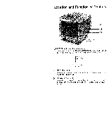
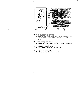
RGB input selectors Depending on the RGB output of the equipment you have connec' ed, set these switches to one of the following four positions. ANALOG: For microcomputers having analog RGB output, such as those using the PGA card. The position of the left switch has no effect when the right switch is set to ANALOG. L NORM D1 D NORM-DIGITAL: For microcom- 1 I puters having TTL RGB output, such as the IBM 3270. ,® NORM Dl D2 DIGITAL ANALOG DIGITAL ANALOG D1-DIGITAL: For microcomputers having TTL RGB and I signal output, such as the IBM NORM D1 D2 PC, AT and XT using the standard color graphics card. DIGITAL ANALOG D2-DIGITAL: For TTL graphics cards on the IBM PC, AT and XT. (automatic adjustrnent be- NORM 1 D2 tween EGA, CGA and MDA) 1 DIGITAL ANALOG RGB IN (input) connector (9-pin D-sub) Allows a microcomputer having either analog or digital RGB output to be connected. Refer to page 8. (13 AC IN connector Connect to the AC outlet with the supplied AC power cord. 7
-
 1
1 -
 2
2 -
 3
3 -
 4
4 -
 5
5 -
 6
6 -
 7
7 -
 8
8 -
 9
9 -
 10
10 -
 11
11 -
 12
12 -
13
-
14
-
15
-
16
-
17
-
18
-
19
-
20
-
21
-
22
-
23
-
24
-
25
-
26
-
27
-
28
-
29
-
30
-
31
-
32
-
33
-
34
-
35
-
36
-
37
-
38
 |
 |
