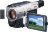
Sony DCR TRV520 Operating Instructions - Page 126
SEL/PUSH EXEC dial, Power Zoom lever
 |
UPC - 027242569997
View all Sony DCR TRV520 manuals
Add to My Manuals
Save this manual to your list of manuals |
Page 126 highlights
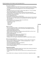
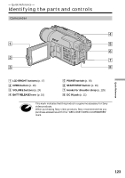
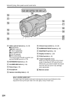
Identifying the parts and controls el rg rh r; rj ra rk rs rl t; rd ta rf ts el Intelligent accessory shoe r; DATA CODE button (p. 25) ra DISPLAY button (p. 25) rs Lithium battery compartment (p. 107) rd PB ZOOM button (p. 51, 94) rf TITLE button (p. 44) rg Power Zoom lever (p. 18) rh "Memory Stick" lamp This lamp lights up while "Memory Stick" is in the "Memory Stick" compartment. rj PHOTO button (p. 29, 77) rk DIGITAL EFFECT button (p. 38, 50) rl END SEARCH button (p. 23) t; PICTURE EFFECT button (p. 36, 49) ta MENU button (p. 32, 64) ts SEL/PUSH EXEC dial (p. 32, 64) Notes on the intelligent accessory shoe •The intelligent accessory shoe supplies power to optional accessories such as a video light or microphone. •The intelligent accessory shoe is linked to the POWER switch, allowing you to turn the power supplied by the shoe on and off. Refer to the operating instructions of the accessory for further information. •The intelligent accessory shoe has a safety device for fixing the installed accessory securely. To connect an accessory, press down and push it to the end, and then tighten the screw. •To remove an accessory, loosen the screw, and then press down and pull out the accessory. 126
-
 1
1 -
2
-
3
-
4
-
5
-
6
-
7
-
8
-
9
-
10
-
11
-
12
-
13
-
14
-
15
-
16
-
17
-
18
-
19
-
20
-
21
-
22
-
23
-
24
-
25
-
26
-
27
-
28
-
29
-
30
-
31
-
32
-
33
-
34
-
35
-
36
-
37
-
38
-
39
-
40
-
41
-
42
-
43
-
44
-
45
-
46
-
47
-
48
-
49
-
50
-
51
-
52
-
53
-
54
-
55
-
56
-
57
-
58
-
59
-
60
-
61
-
62
-
63
-
64
-
65
-
66
-
67
-
68
-
69
-
70
-
71
-
72
-
73
-
74
-
75
-
76
-
77
-
78
-
79
-
80
-
81
-
82
-
83
-
84
-
85
-
86
-
87
-
88
-
89
-
90
-
91
-
92
-
93
-
94
-
95
-
96
-
97
-
98
-
99
-
100
-
101
-
102
-
103
-
104
-
105
-
106
-
107
-
108
-
109
-
110
-
111
-
112
-
113
-
114
-
115
-
116
-
117
-
118
-
119
-
120
-
 121
121 -
 122
122 -
 123
123 -
 124
124 -
 125
125 -
 126
126 -
 127
127 -
 128
128 -
 129
129 -
 130
130 -
 131
131 -
132
 |
 |
