Sony DMXWL1 Reference Guide
Sony DMXWL1 - BRAVIA Wireless HD Link Manual
 |
UPC - 027242744592
View all Sony DMXWL1 manuals
Add to My Manuals
Save this manual to your list of manuals |
Sony DMXWL1 manual content summary:
- Sony DMXWL1 | Reference Guide - Page 1
3-877-083-11(1) Reference Guide The Reference Guide contains troubleshooting, specifications, and safety related information. DMX-WL1 © 2008 Sony Corporation - Sony DMXWL1 | Reference Guide - Page 2
your Sony dealer regarding this product. Transmitter Model No. DMX-WL1T Serial No. Receiver DMX-WL1R manual could void your authority to operate this equipment. For Customers in Canada This Class B digital apparatus complies with Canadian ICES-003. Trademark Information "BRAVIA" and Sony - Sony DMXWL1 | Reference Guide - Page 3
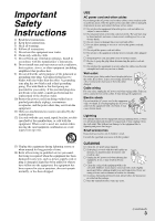
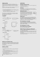
block any ventilation openings. Install in accordance with the manufacturer's instructions. 8) Do not install near any heat sources such as or any other cables is damaged, stop using it at once and contact the Sony service center. s Do not place the equipment where the power cord and cables are - Sony DMXWL1 | Reference Guide - Page 4
may cause a fire or damage to the equipment. Transmitter Horizontal 3/8 inches (1 cm) 3/8 inches (1 cm service technician to dispose of the equipment. For Customers in Canada To prevent radio interface to the licensed service back of the TV, do not use the receiver as a handle to pick up the TV set - Sony DMXWL1 | Reference Guide - Page 5
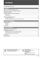
-alone Near the TV 18 Installing the Receiver Unit on the Wall 19 Specifications ...20 Troubleshooting ...21 Startup Guide (separate volume) The Startup guide explains how to connect, setup and use your wireless link. Customer Support http://www.sony.com/tvsupport On-line Registration United - Sony DMXWL1 | Reference Guide - Page 6
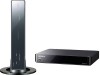
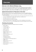
. The Wireless Link supports connection for up to four HDMI sources and 1 component source. Optimal Environment for Placement of the Units Follow the suggestions below to create an optimal environment for your new Sony BRAVIA Wireless Link. Proper placement of the receiver and transmitter units will - Sony DMXWL1 | Reference Guide - Page 7
with AC cord. Connects to any HDMI input on the TV. HDMI (High-Definition Multimedia Interface) provides an uncompressed, all-digital audio/video interface between the receiver unit and the TV. ~ • Be sure to use only an HDMI cable that bears the HDMI logo. These jacks are for service only. 7 - Sony DMXWL1 | Reference Guide - Page 8
IN IR BLASTER DIGITAL AUDIO OUT 1 (OPTICAL) SERVICE 9 0 qa qs qd Item Description 1 POWER Press to turn the transmitter unit on and off. 2 POWER LED Lights up in green when the transmitter unit is turned on. 3 LINK LEVEL LED Lights up in green to indicate the quality of the wireless - Sony DMXWL1 | Reference Guide - Page 9
compatible. This unit supports Linear PCM and compressed audio format, such as Dolby Digital Audio, DTS audio, with a maximum bitrate of 3 Mbps or less. If the connected equipment and TV support compressed audio formats, the transmitter unit will output compressed audio. This jack is for service - Sony DMXWL1 | Reference Guide - Page 10
TV POWER POWER 2 IN 1 COMPONENT IN 5 HDMI IN 2 IN 3 IN 4 DISPLAY TV 4 5 6 PICTURE WIDE CC FREEZE 7 8 MENU 123 9 456 789 0 0 ENT qa VOL CH qs MUTING JUMP REC REC PAUSE REC STOP BD/DVD TOP MENU MENU F1 F2 CONNECT SETUP WIRELESS LINK Button Description 2 TV function button qh - Sony DMXWL1 | Reference Guide - Page 11
• x: Stops the playback. 6 GUIDE Press to display the Digital Electronic Program Guide (EPG) when the satellite receiver or cable box is selected. 7 wireless channel if the LINK LEVEL is low or the picture is noisy or the sound quality is diminished. ~ • You must setup the IR Blaster before - Sony DMXWL1 | Reference Guide - Page 12
5 HDMI IN 2 IN 3 IN 4 DISPLAY TV PICTURE WIDE CC FREEZE MENU 123 456 789 0 ENT VOL CH MUTING JUMP REC REC PAUSE REC STOP BD/DVD TOP MENU MENU F1 F2 CONNECT SETUP Button Description qj POWER qj qk qk DISPLAY Press to turn the transmitter unit on and off. ~ • The receiver unit - Sony DMXWL1 | Reference Guide - Page 13
IR Blaster Setup/IR Blaster/HDMI 1 Category BD Maker Sony Code BD 1 Te s t ( Po w e r O n / O f f ) Save and Exit Set up the IR Blaster to control external equipment connected to the transmitter unit with the supplied remote control. For details, see the supplied Startup Guide. Category - Sony DMXWL1 | Reference Guide - Page 14
Language Language Setup IR Blaster Language English Español Français Software Version 1.00.00 Select a language from English, Español and Français. 14 - Sony DMXWL1 | Reference Guide - Page 15
IR Code List Cable Box Manufacturer Code Sony Cable 1(2177), Cable DVR(2181) ABC 0003, 0237, 0008, 0033 ADB 2586 Amino 1822 Digeo 1187 General 0476, 0810, 0003 Instrument GoldStar 0144 Hamlin 0273 Jerrold 0476, 0810, 0003 Motorola 1376, 0476, 0810, 1187 Myrio 1822 Oak - Sony DMXWL1 | Reference Guide - Page 16
1516), BD 2(2178), BD 3(2180) 0741 1641 2084 0142 0199 2250 Receiver Manufacturer Sony Aiwa Bose Denon Harman/Kardon Hitachi Insignia JVC Kenwood LG Marantz McIntosh Onkyo your equipment is not listed, please visit http://www.sonystyle.com/dmxwl1 for a complete list of supported codes. 16 - Sony DMXWL1 | Reference Guide - Page 17
unit can also be used vertically with the supplied stand. 1 Match the Guide Pin on the center of the stand and the screw hole on the right side of the transmitter unit. Guide Pin Attaching the Receiver Unit Attaching the Receiver Unit to the Rear of the TV 1 Attach the supplied TV Mounting bracket - Sony DMXWL1 | Reference Guide - Page 18
horizontally on a table or stand. Place the Receiver Unit Stand-alone Near the TV If the Wireless LINK LEVEL is still low, place the receiver unit horizontally near the TV. Find a location where all LINK LEVEL LEDs are lit. Guide Pin ~ • Be sure to remove the receiver unit from the back of the TV - Sony DMXWL1 | Reference Guide - Page 19
Other Information Installing the Receiver Unit on the Wall The receiver unit can be installed on a wall with the supplied Wall-Mount bracket. Be . Less than 2.5 mm Screw (not supplied) 2 Align the slider on the bottom of the receiver unit with the groove of the Wall-Mount bracket. 3 Slide the - Sony DMXWL1 | Reference Guide - Page 20
bitrate of 3 Mbps or less. AUDIO (IN 1 HDMI only): 500 mVrms / Impedance: 47 kilohms DIGITAL AUDIO OUT (OPTICAL) Optical Digital Audio Output (PCM or IEC61937 compressed audio format with a maximum bitrate of 3 Mbps or less) IR BLASTER 3.5 mm Mini jack SERVICE For service use only. DC IN DC - Sony DMXWL1 | Reference Guide - Page 21
Information Troubleshooting If you have questions, service needs, or require technical assistance related to the use of your Sony BRAVIA Wireless Link, please visit our website or call one of the following numbers: http://www.sony.com/tvsupport 1-866-918-2485 for US Support 1-877-899-SONY(7669 - Sony DMXWL1 | Reference Guide - Page 22
the Initial Setup menu appears. Follow the instructions to complete initial setup. • Put the IR Blaster in a location visible to the IR receiver of the equipment. • The power of the receiver unit turns on or off in conjunction with TV if HDMI Control or Control for HDMI of the TV is On and the unit - Sony DMXWL1 | Reference Guide - Page 23
- Sony DMXWL1 | Reference Guide - Page 24
or Startup Guide • Experience difficulty operating your module For United States http://www.sony.com/tvsupport or to speak with a support representative: 1-866-918-2485 For Canada http://www.sony.ca/support or to speak with a support representative: 1-877-899-SONY (7669) Sony will work to
-
 1
1 -
 2
2 -
 3
3 -
 4
4 -
 5
5 -
 6
6 -
 7
7 -
8
-
9
-
10
-
11
-
12
-
13
-
14
-
15
-
16
-
17
-
18
-
19
-
20
-
21
-
22
-
23
-
24
 |
 |
3-877-083-
11
(1)
© 2008 Sony Corporation
Reference Guide
The Reference Guide contains troubleshooting, specifications, and safety
related information.
DMX-WL1