Sony F35 Product Manual (F35 Operation Manual) - Page 51
Viewing the FUNCTION (Format/Switch Function) Display, 3-6-5 Setting the Marker Indications
 |
View all Sony F35 manuals
Add to My Manuals
Save this manual to your list of manuals |
Page 51 highlights
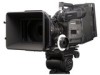
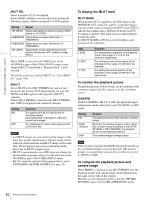
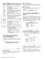
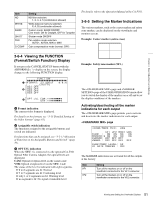
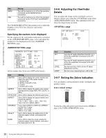
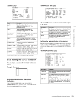
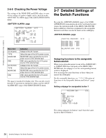
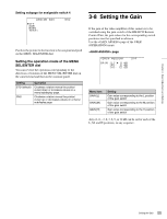
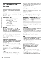
Chapter 3 Basic Adjustments and Settings Item ND WHITE 5600K SHUTT FAN G-COMP Setting ND filter selection: 1, 2, 3, 4, 5 (combination allowed) White balance memory selection: P, A, B (combination allowed) Custom mode: 5600K ON/OFF Cine mode: ON for Daylight, OFF for Tungsten Shutter mode ON/OFF Fan rotation mode selection: AUTO1, AUTO2, MIN or MAX Gain compensation mode (normal: OFF) For details, refer to the Operation Manual of the CA-F101. 3-6-5 Setting the Marker Indications The various markers, such as the center marker and safety zone marker, can be displayed on the viewfinder and monitor screens. Example: Center marker (entire cross) 3-6-4 Viewing the FUNCTION (Format/Switch Function) Display If you press the CANCEL/STATUS button with the ABNORMAL< ! > display on the screen, the display changes to the following FUNCTION display: FUNCTION 1 FORMAT: 23.98PsF (24)FPS AS1:OFF 2 AS2:OFF AS3:OFF AS4:OFF 4:4:4 3 OPT LVL CAM:xxxxxxxxb V T R : xxxxxxxxb a Format indication The current video format is displayed. For details on the formats, see "3-13 Detailed Setting of the Video Format" (page 61). b Assignable switch indication The functions assigned to the assignable buttons and switch are indicated. For functions that can be assigned, see "3-2-11 Allocation of Functions to the Assignable Buttons and Switch" (page 39). c OPT LVL indication When the SRW-1 is connected via the optional CA-F101 Optical Fiber Camera Adapter, the optical levels are displayed. CAM: Optical reception level on the camera side VTR: Optical reception level on the SRW-1 side The status of the level is indicated with eight segments. If 6 to 8 segments are lit: Normal If 3 to 5 segments are lit: Cautioning level If only 1 or 2 segments are lit: Warning level If no segment is lit: No signal or unusable level Example: Safety zone marker (90%) The page and page of the USER (OPERATION) menu allow you to switch the display of the markers on or off and to set the display conditions of the markers. Activating/deactivating all the marker indications for each output The page permits you to activate and deactivate the marker indications for each output. page U09 VF1 CHAR : ON MARKER:B ON CURSOR: OFF ZEBRA : OFF VF2 ON ON OFF OFF MONI ON ON OFF OFF VBS ON ON OFF CHAR/MARK LEVEL: 50 VF GATE MARKER : OFF The MARKER indications are activated for all the outputs at the factory. Item VF1 VF2 Setting Turn all the markers on or off on the viewfinder connected to the VF1 connector. Turn all the markers on or off on the viewfinder connected to the VF2 connector. 51 Viewing and Setting the Viewfinder Displays
-
 1
1 -
2
-
3
-
4
-
5
-
6
-
7
-
8
-
9
-
10
-
11
-
12
-
13
-
14
-
15
-
16
-
17
-
18
-
19
-
20
-
21
-
22
-
23
-
24
-
25
-
26
-
27
-
28
-
29
-
30
-
31
-
32
-
33
-
34
-
35
-
36
-
37
-
38
-
39
-
40
-
41
-
42
-
43
-
44
-
45
-
 46
46 -
 47
47 -
 48
48 -
 49
49 -
 50
50 -
 51
51 -
 52
52 -
 53
53 -
 54
54 -
 55
55 -
 56
56 -
57
-
58
-
59
-
60
-
61
-
62
-
63
-
64
-
65
-
66
-
67
-
68
-
69
-
70
-
71
-
72
-
73
-
74
-
75
-
76
-
77
-
78
-
79
-
80
-
81
-
82
-
83
-
84
-
85
-
86
-
87
-
88
-
89
-
90
-
91
-
92
-
93
-
94
-
95
-
96
-
97
-
98
-
99
-
100
-
101
-
102
-
103
-
104
-
105
-
106
-
107
-
108
-
109
-
110
-
111
-
112
-
113
-
114
-
115
-
116
-
117
-
118
-
119
-
120
-
121
-
122
-
123
-
124
-
125
-
126
-
127
-
128
-
129
-
130
-
131
-
132
-
133
-
134
-
135
-
136
-
137
-
138
-
139
-
140
-
141
-
142
 |
 |