Sony FWD-42PV1A Protocol Manual - Page 17
MainPowerVs, Enable, MainPowerVa, AnalogPower12V, 0x00-0xFF, Temp2, Temp3, 12V, 9V, Reserved, Panel
 |
View all Sony FWD-42PV1A manuals
Add to My Manuals
Save this manual to your list of manuals |
Page 17 highlights
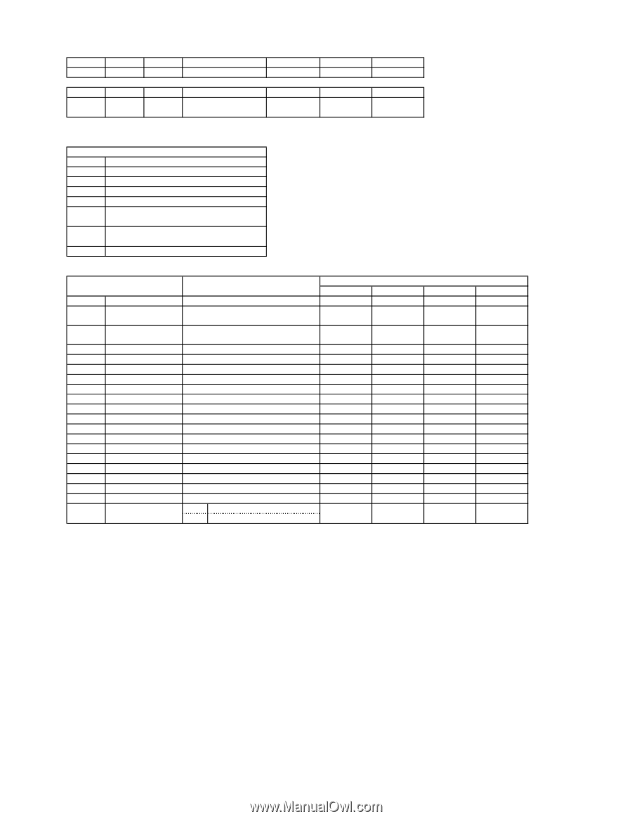
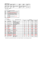
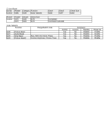
(g)Shutdown Log Syntax Header Enquiry 0x83 Category Function 0x30 0x11 Data1 0xFF Data2 0xFF Check Sum 0xC0 Answer Header Answer Return to Data Size Enquiry 0x70 0x00 0x02 Return Data1: 0x00-0xFF Return Data1 Check Sum Shutdown 0xXX Completed Log Code Table(4-c) Shutdown Information bit0 Reserved bit1 1: FAN Movement Abnormal, 0: Normal bit2 1: Panel communication Abnormal, bit3 1: Temperature Sensor Abnormal, 0: bit4 1: Main Power Abnormal, 0: Normal bit5 1: Digital Power Abnormal (3.3V, 5V) 0: Normal bit6 1: Analog Power Abnormal (12V, 9V) 0: Normal bit7 Reserved Code Table(4-d) [a]Function [b]Range/Switch code 0x00 0x01 0x02 0x03 0x07 0x08 0x09 0x0A 0x0B 0x0C 0x0D 0x0F 0x10 0x11 0x12 0x13 0x14 0x15 0x16 0x20 Model Name 0x08-0x09 Serial Number 0x001E8480-0x002DC6BF Operation Time (2,000,000-2,999,999) 0x00000000-0xD693A3FF (0sec.-3,599,999,999sec.) Soft Version(Main) 0x0000-0xFFFF Digital 3.3v 0x00-0xFF MainPower(Vs) 0x00-0xFF Digital 5v 0x00-0xFF Temp1 0x00-0xFF Temp2 0x00-0xFF Temp3 0x00-0xFF Temp(P/S) 0x00-0xFF Soft Version(Scaler) 0x0000-0xFFFF Analog9V 0x00-0xFF Shutdown Log 0x00-0xFF Digital 3.3v(Failure) 0x00-0xFF Digital 5v(Failure) 0x00-0xFF Analog5V/9V(Failure)0x00-0xFF MainPower(Va) 0x00-0xFF AnalogPower12V 0x00-0xFF Busy to INPUT* 0x00 Non Busy 0x01 Busy Control No Yes Yes No No No No No No No No No No No No No No No No No Command Enquiry Standby Yes Enable Yes Enable Yes Enable Yes Enable Yes Enable Yes Enable Yes Enable Yes Enable Yes Enable Yes Enable Yes Enable Yes Enable Yes Enable Yes Enable Yes Enable Yes Enable Yes Enable Yes Enable Yes Enable Yes Enable * Check Busy first, and then check Non Busy. If only checking Non Busy, it may not be detected correctly. Power On Enable Enable Enable Enable Enable Enable Enable Enable Enable Enable Enable Enable Enable Enable Enable Enable Enable Enable Enable Enable
-
 1
1 -
2
-
3
-
4
-
5
-
6
-
7
-
8
-
9
-
10
-
11
-
 12
12 -
 13
13 -
 14
14 -
 15
15 -
 16
16 -
 17
17 -
 18
18
 |
 |