Sony HCD-MDX10 Service Manual
Sony HCD-MDX10 - Compact Disk Deck Receiver Component Manual
 |
View all Sony HCD-MDX10 manuals
Add to My Manuals
Save this manual to your list of manuals |
Sony HCD-MDX10 manual content summary:
- Sony HCD-MDX10 | Service Manual - Page 1
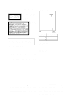
HCD-MDX10 SERVICE MANUAL Ver 1.1 2001. 06 US Model Canadian Model AEP Model UK Model E Model Australian Model HCD-MDX10 is the tuner, deck, CD, MD and amplifier section in MHC-MDX10. CD SECTION MD SECTION TAPE DECK SECTION Model Name Using Similar Mechanism NEW Mechanism Type CDM38LH-5BD32L - Sony HCD-MDX10 | Service Manual - Page 2
- 2 - - Sony HCD-MDX10 | Service Manual - Page 3
. For details on how to view error codes for the customer, refer to the following box in the instruction manual. For details on how to check error codes during servicing, refer to the following "Procedure for using the SelfDiagnosis Function (Error History Display Mode)". Procedure for using the - Sony HCD-MDX10 | Service Manual - Page 4
ITEMS OF ERROR HISTORY MODE ITEMS AND CONTENTS Selecting the Test Mode Display total rec Details of History Displays the recording time. Displayed as "rππππππh". The displayed time is the total time the laser is set to the high power state. This is about 1/4 of the actual recording time. The time - Sony HCD-MDX10 | Service Manual - Page 5
DOTTED LINE WITH MARK ! ON THE SCHEMATIC DIAGRAMS AND IN THE PARTS LIST ARE CRITICAL TO SAFE OPERATION. REPLACE THESE COMPONENTS WITH SONY PARTS WHOSE PART NUMBERS APPEAR AS SHOWN IN THIS MANUAL OR IN SUPPLEMENTS PUBLISHED BY SONY. ATTENTION AU COMPOSANT AYANT RAPPORT À LA SÉCURITÉ!! LES COMPOSANTS - Sony HCD-MDX10 | Service Manual - Page 6
SAFETY CHECK-OUT After correcting the original service problem, perform the following safety checks before releasing the set to the customer: Check the antenna terminals, metal trim, "metallized" knobs, screws, and all other exposed metal parts for AC leakage. Check leakage as described below. - Sony HCD-MDX10 | Service Manual - Page 7
and BD (MD) Board 19 3-8. SW Board and Loading Motor (M103 19 4. SERVICE MODE 20 9. EXPLODED VIEWS 9-1. Case Section 119 9-2. Chassis Section 120 9-3. Front Panel 127 9-10. MD Mechanism Section-2 (MDM-5A 128 10. ELECTRICAL PARTS LIST 129 5. TEST MODE (MD 22 6. MECHANICAL ADJUSTMENTS 26 - Sony HCD-MDX10 | Service Manual - Page 8
SECTION 1 SERVICING NOTE HOW TO OPEN THE DISC TRAY WHEN POWER SWITCH TURNS OFF 1 Remove the Case. 3 Pull-out the disc tray. 2 Turn the cam to the - Sony HCD-MDX10 | Service Manual - Page 9
JIG FOR CHECKING BD BOARD WAVEFORM The special jig (J-2501-149-A) is useful for checking the waveform of the BD board. The names of terminals and the checking items to be performed are shown as follows. GND : Ground I+3V : For measuring IOP (Check the deterioration of the optical pick-up laser) IOP - Sony HCD-MDX10 | Service Manual - Page 10
With the power ON, press the CD-MD SYNC button while pressing the p and ENTER/YES buttons together. 2. Rotate the AMS dial to display "Service", and press the YES button. 3. Rotate the AMS dial to display "lop.Read". 4 is displayed and the recorded contents are displayed. @@.@ : indicates the Iop - Sony HCD-MDX10 | Service Manual - Page 11
CHECKS PRIOR TO PARTS REPLACEMENT AND ADJUSTMENTS Before performing repairs, perform the following checks to determine the faulty locations up to a certain extent. Details of the procedures are described - Sony HCD-MDX10 | Service Manual - Page 12
on the fluorescent indicator tube. During playback, the "track mode" for obtaining track information will be set. This is useful for locating the faulty part of the unit. • The following will be displayed : During recording and stop : Retry cause, number of retries, and number of retry errors - Sony HCD-MDX10 | Service Manual - Page 13
Reading the Track Mode Display Higher Bits Lower Bits Hexadecimal 8 4 2 1 8 4 2 1 Hexa- Bit decimal b7 b6 b5 b4 b3 b2 b1 b0 When 0 Details When 1 Binary 0 0 0 0 0 0 0 1 01 Emphasis OFF Emphasis ON 0 0 0 0 0 0 1 0 02 Monaural Stereo 0 0 0 0 0 1 0 0 04 This is 2-bit display. Normally 01. - Sony HCD-MDX10 | Service Manual - Page 14
Front Panel SECTION 2 GENERAL 1 2 34 5 67 8 9 64 63 62 61 60 59 58 57 56 55 54 53 52 51 50 49 48 47 46 45 44 43 42 41 40 10 11 12 13 14 15 16 17 18 19 20 25 21 22 23 24 29 26 27 28 30 31 32 33 34 35 39 38 37 36 - 14 - - Sony HCD-MDX10 | Service Manual - Page 15
LOCATION OF PARTS AND CONTROLS 1 1/u (POWER) button and indicator 2 REC button and indicator 3 REC IT button 4 CD-MD SYNC button 5 DISC SKIP/EX-CHANGE EQ indicator 62 EFFECT indicator 63 Display Window 64 POWER SAVE/DEMO (STANDBY) button This section is extracted from instruction manual. - 15 - - Sony HCD-MDX10 | Service Manual - Page 16
SECTION 3 DISASSEMBLY Note: Follow the disassembly procedure in the numerical order given. 3-1. LOADING PANEL Claws 3 Loading panel 2 Pull-out the disc tray. 1 Turn the cam to the direction of arrow. 3-2. MD MECHANISM AND FRONT PANEL 8 MD mechanism 3 Wire !∞ Flat type wire (CN303) !¢ Flat type - Sony HCD-MDX10 | Service Manual - Page 17
3-3. CASSETTE LID AND TAPE MECHANISM 9 Tape mechanism 8 Three screws (BVTP2.6x8) 7 Two screws (BVTP2.6x8) 3 Cassette lid (R) block 4 Cassette lidr (L) block 2 Releas 6 Spring (L) Portion B Portion A 5 Spring (R) 1 Release Note for installation Portion B Portion A 3-4. MD LINK, POWER SW, CD - Sony HCD-MDX10 | Service Manual - Page 18
4 Two claws 2 Pull-out the disc tray. 5 Remove the disc tray. Claw A 1 Turn the cam the direction of arrow. 3-6. SLIDER (CAM) 6 Slider (Cam) 2 Bracket (Guide L) 1 Two screws (BTP2.6x6) Set the shaft of Cam gear to be at the position in the figure. Claw B 3 Leaf spring Set the shaft of - Sony HCD-MDX10 | Service Manual - Page 19
3-7. BASE UNIT (MBU-5A) AND BD (MD) BOARD 5 Flexible board (CN104) 6 Flexible board (CN101) 2 Base unit (MBU-5A) 1 Three screws (BTP2.6x6) 7 BD (MD) board 3 Remove the solder (Five portion) 4 Screw (M1.7x4) 3-8. SW BOARD AND LOADING MOTOR (M103) 2 Gear B 3 Two screws (PWH1.7x3) 1 Screw (PTPWH - Sony HCD-MDX10 | Service Manual - Page 20
SECTION 4 SERVICE MODE MC Cold Reset • The cold reset clears all data including preset data stored in the RAM to initial conditions. Execute this mode when returning - Sony HCD-MDX10 | Service Manual - Page 21
AMS Test Mode • This mode is used for checking the AMS operations of the tape deck. JIG 7-819-039-12 Alignment tape, AMS-110A Procedure: 1. Press the 1/u button to turn the unit ON. 2. Set the tape (AMS-110A). 3. Press the three buttons p , ENTER/YES , and DISC 3 button simultaneously. 4. "TEST MODE - Sony HCD-MDX10 | Service Manual - Page 22
. When the test mode is set, "Check" will be displayed. Rotating the AMS dial switches between the following four groups; ···Nn Check Nn Adjust Nn Service Nn Develop Nn ···. Procedure 2: With the power ON, press the REC (MD) button while pressing the p and ENTER/YES buttons together. When the test - Sony HCD-MDX10 | Service Manual - Page 23
. Refer to "Group" in the table for details selected. All items used for servicing can be treated using group S. So be carefully not to enter other groups by ADJUST LDPWR ADJUST EF MO ADJUST EF CD ADJUST FBIAS ADJUST EEP MODE MANUAL CMD SVDATA READ ERR DP MODE SLED MOVE ACCESS MODE 0920 CHECK HEAD - Sony HCD-MDX10 | Service Manual - Page 24
display as below. "CPLAY MID" n "CPLAY OUT" n "CPLAY IN" When pressed another time, the parts to be played back can be moved. 2 When access completes, the display changes to "C1 = AD memory. It is not used in servicing. If set accidentally, press the MENU/NO button immediately to exit it. - 24 - - Sony HCD-MDX10 | Service Manual - Page 25
address. a = Indicates the ADIP address. Mode display Error rate display Address display Auto gain display (Not used in servicing) Detrack check display (Not used in servicing) IVR display (Not used in servicing) Note: "-" is displayed when servo is not imposed. 4. Auto gain display (Not used in - Sony HCD-MDX10 | Service Manual - Page 26
demagne- tizer. 3. Do not use a magnetized screwdriver for the adjustments. 4. After the adjustments, apply suitable locking compound to the parts adjusted. 5. The adjustments should be performed with the rated power sup- ply voltage unless otherwise noted. Torque Measurement Mode Torque - Sony HCD-MDX10 | Service Manual - Page 27
check • Traverse check • Focus bias check • C PLAY check • Self-recording/playback check OK • Abbreviation OP : Optical pick-up OWH: Overwrite head NG Parts Replacement and Repair Check the sleding and spindle mechanisms. Other causes can be suspected. Has the OWH been replaced? YES NO Has OP - Sony HCD-MDX10 | Service Manual - Page 28
FOR ADJUSTMENTS 1) When replacing the following parts, perform the adjustments and checks with ¬ be checked without the need to solder. (Refer to Servicing Note on page 9.) 7) As the disc used will is convenient. It sharply reduces the time and trouble to set the laser power meter sensor onto the - Sony HCD-MDX10 | Service Manual - Page 29
7-6. CHECKS PRIOR TO REPAIRS These checks are performed before replacing parts according to "approximate specifications" to determine the faulty locations. For details, refer to "Checks Prior to Parts Replacement and Adjustments" (See page 11). 7-6-1. Temperature Compensation Offset Check When - Sony HCD-MDX10 | Service Manual - Page 30
10.Observe the waveform of the oscilloscope, and check that the specified value is satisfied. Do not rotate the AMS dial. (Traverse Waveform) A VC B Specified value : Below 10% offset value Offset value (%) = IA - BI X 100 2 (A + B) 11. Press the ENTER/YES button display "EF MO CHECK" The disc - Sony HCD-MDX10 | Service Manual - Page 31
the p and ENTER/YES buttons together. 2. Rotate the AMS dial to display "Service", and press the EN- TER/YES button. 3. Rotate the AMS dial to display has been replaced, perform this adjustment after the temperature of this part has become the ambient temperature. Adjusting Procedure : 1. Rotate the - Sony HCD-MDX10 | Service Manual - Page 32
. 2%. Adjust the waveform so that the specified value is satisfied as much as possible. (Write power traverse adjustment) (Traverse Waveform) A VC B Specification A = B 9. Press the ENTER/YES button, and save the adjustment results in the non-volatile memory. ("EFB = SAVE" will be displayed for - Sony HCD-MDX10 | Service Manual - Page 33
waveform varies at intervals of approx. 2%. Adjust the waveform so that the specified value is satisfied as much as possible. (Traverse Waveform) A VC B Specification A = B 12. Press the ENTER/YES button, and save the adjustment results in the non-volatile memory. ("EFB = SAVE" will be displayed for - Sony HCD-MDX10 | Service Manual - Page 34
7-13. ERROR RATE CHECK 7-13-1. CD Error Rate Check Checking Procedure : 1. Load a check disc (MD) TDYS-1. 2. Rotate the AMS dial and display "CPLAY MODE". 3. Press the ENTER/YES button twice and display "CPLAY MID". 4. The display changes to "C1 = AD = ". 5. Check that the C1 error rate is below 20 - Sony HCD-MDX10 | Service Manual - Page 35
7-16. ADJUSTING POINTS AND CONNECTING POINTS [BD BOARD] (SIDE A) CN101 D101 CN110 GND I+3V IOP TE RF VC NOTE IC171 [BD BOARD] (SIDE B) IC101 IC121 IC192 NOTE:It is useful to use the jig. for checking the waveform. (Refer to Servicing Note on page 9.) - 35 - - Sony HCD-MDX10 | Service Manual - Page 36
adjustments, apply suitable locking compound to the parts adjusted. 4. The adjustments should be performed with the rated power sup- ply voltage unless otherwise noted. 5. The adjustments should be performed in the order given in this service manual. (As a general rule, playback circuit adjustment - Sony HCD-MDX10 | Service Manual - Page 37
Tape Speed Adjustment (Deck A) Note: Set the test mode using the following method and begin tape speed adjustment. In the test mode, the speed will switch to double speed or normal speed each time the HI DUB button is pressed. Procedure: With the power turned ON, press the p button, ENTER/NEXT - Sony HCD-MDX10 | Service Manual - Page 38
Record Level Adjustment (Deck B) Procedure: INTRODUCTION When set to the test mode performed in Tape Speed Adjustment, when the tape is rewound after recording, the "REC memory mode" which rewinds only the recorded portion and playback is set. This "REC memory mode" is convenient for performing - Sony HCD-MDX10 | Service Manual - Page 39
After check, remove the lead wire connected in step 2. TP (RF) TP (AGCCON) TP (FE) TP (TE) TP (FE1) 8-1. CIRCUIT BOARDS LOCATION SECTION 8 DIAGRAMS HCD-MDX10 STANDBY board MD LINK board MD DIGITAL board DISPLAY board ENCAPSULATED COMPONENT (US,CND,AR,KR,SP,MY,HK,AUS) TUNER unit (AEP,UK - Sony HCD-MDX10 | Service Manual - Page 40
HCD-MDX10 8-2. BLOCK DIAGRAMS - BD (CD) SECTION - OPTICAL PICK-UP BLOCK (KSS-213D/K-NP) DETECTOR E AC BD VCC VC A C D B F 5A 7C 8D 6B IC103 RF AMP RF - Sony HCD-MDX10 | Service Manual - Page 41
29 SFDR 30 SRDR 3 SPFD 4 SPRD PSB 16 XRST - 43 - EEP ROM IC171 SDA 5 SCL 6 DETECT SW S101, S102, S601-604 M103 LOADING MOTOR M - 44 - HCD-MDX10 DIN0 DIN1 B MAIN SECTION (Page 48) ADDT SCTX XINT DADT DOUT (NON CONNECT) BCK LRCK 512FS SQSY DQSY MNT3 MNT2 MNT1 MNT0 SENS SRDT SCLK - Sony HCD-MDX10 | Service Manual - Page 42
HCD-MDX10 - BD (MD) SECTION (2) - ADDT BCK LRCK DADT IC202 IC202 9 8 11 10 A/D,D/A CONVERTER IC201 18 DATAO VINL1 2 VINL2 6 VINR1 4 R-CH VINR2 8 R-CH VOUTL 26 VOUTR 24 R- - Sony HCD-MDX10 | Service Manual - Page 43
11 HP DET 36 POWER 2 CD POWER 5 FL SW 42 STBY RELAY 43 X601 32.768KHz STK MUTE 1 PROTECTOR ON 27 J191 SUPER WOOFER - 48 - HCD-MDX10 D IN 0 D IN 1 IIC DATA IIC CLK P. DOWN SPEANA WAKE UP STANDBY LED IIC DATA IIC CLK TIMER LED RESET FRONT B BD (MD) SECTION (1) (Page 44 - Sony HCD-MDX10 | Service Manual - Page 44
HCD-MDX10 - DECK SECTION - L HP101 PB HEAD (DECK A) R L REC/PB HEAD (DECK B) R HRPE101 ERASE HEAD X 09 S1004 A CrO2 S1008 B CrO2 IC611 RV311 PLAYBACK LEVEL DECK A R CH IC601 - Sony HCD-MDX10 | Service Manual - Page 45
-613 PANEL LED Q601,602 +5V (LED) LED CONTROL Q603 REMOTE 2 CONTROL RECEIVER IC602 S601 (JOG) ROTARY ENCODER KEY MATRIX ROTARY ENCODER S602 VOLUME - 51 - HCD-MDX10 - 52 - - Sony HCD-MDX10 | Service Manual - Page 46
HCD-MDX10 - MAIN POWER/SUB POWER SECTION - F RELAY FRONT J MAIN SECTION (Page 48) DBFB STK MUTE RY-SW PROTECTOR AC CUT MD H+5V RDS D+5V UN SW D+ - Sony HCD-MDX10 | Service Manual - Page 47
line with mark ! are critical for safety. Replace only with part number specified. Note: Les composants identifiés par une marque XBCK) 7 3.8Vp-p 11.29MHz IC121 @ª (FS256) 8 3.2Vp-p 176.4kHz IC121 (º (FS4) HCD-MDX10 - MAIN (3/4) SECTION - 1 5.2Vp-p 32.768kHz IC501 !¡ XC-OUT 2 5.5Vp-p 16MHz IC501 - Sony HCD-MDX10 | Service Manual - Page 48
HCD-MDX10 8-3. PRINTED WIRING BOARD - BD (CD) SECTION - • See page 40 for Circuit Boards Location. - 57 - (VC) (RP) (AGCCON) (FE) (TE) (FF1) (Page 75) 19 - 58 - - Sony HCD-MDX10 | Service Manual - Page 49
8-4. SCHEMATIC DIAGRAM - BD (CD) SECTION - • See page 55 for Waveforms. 220 19P NC C (Page 67) TP (TE) TP (FE) TP (RP) TP (AGCCON) TP (VC) 68 10V HCD-MDX10 - 59 - - 60 - - Sony HCD-MDX10 | Service Manual - Page 50
HCD-MDX10 8-5. PRINTED WIRING BOARD - BD (MD) SECTION - • See page 40 for Circuit Boards Location. • Semiconductor Location Ref. No. Location D101 A-1 D181 D-3 D183 D-3 IC103 B-1 IC123 D-2 IC171 D-1 Q102 B-1 - Sony HCD-MDX10 | Service Manual - Page 51
8-6. SCHEMATIC DIAGRAM - BD (MD) (1/2) SECTION - • See page 56 for Waveforms. • See page 109 for IC Block Diagrams. • See page 112 for IC Pin Functions. HCD-MDX10 (Page 65) - 63 - (Page 65) (Page 65) (Page 66) (Page 66) (Page 66) (Page 66) - 64 - - Sony HCD-MDX10 | Service Manual - Page 52
HCD-MDX10 8-7. SCHEMATIC DIAGRAM - BD (MD) (2/2) SECTION - • See page 56 for Waveforms. • See page 109 for IC Block Diagrams. • See page 113 for IC Pin Functions. (Page 63) (Page 63) (Page 63) (Page 64) (Page 64) (Page 64) (Page 64) (Page 93) (Page 93) - 65 - BA033FP-E2 - 66 - - Sony HCD-MDX10 | Service Manual - Page 53
8-8. SCHEMATIC DIAGRAM - MAIN (1/4) SECTION - • See page 75 for Printed Wiring Board. (Page 59) (Page 71) - 67 - HCD-MDX10 MICON INTERFACE (Page 69) (Page 72) (Page 69) - 68 - (Page 73) - Sony HCD-MDX10 | Service Manual - Page 54
HCD-MDX10 8-9. SCHEMATIC DIAGRAM - MAIN (2/4) SECTION - • See page 75 for Printed Wiring Board. (Page 68) (Page 68) (Page 73) - 69 - (Page 74) (Page 74) (Page 104) (Page 74) - 70 - - Sony HCD-MDX10 | Service Manual - Page 55
8-10. SCHEMATIC DIAGRAM - MAIN (3/4) SECTION - • See page 56 for Waveforms. • See page 75 for Printed Wiring Board. • See page 111 for IC Block Diagrams. (Page 67) (Page 100) (Page 100) (Page 91) (Page 67) HCD-MDX10 (Page 73) (Page 73) - 71 - (Page 80) (Page 82) (Page 73) - 72 - - Sony HCD-MDX10 | Service Manual - Page 56
HCD-MDX10 8-11. SCHEMATIC DIAGRAM - MAIN (4/4) SECTION - • See page 75 for Printed Wiring Board. • See page 116 for IC Pin Functions. (Page 68) (Page 72) (Page 69) (Page 72) (Page 69) (Page 70) (Page 70) (Page 72) - 73 - (Page 106) (Page 84) - 74 - - Sony HCD-MDX10 | Service Manual - Page 57
page 40 for Circuit Boards Location. (Page 97) (Page 97) (Page 58) (Page 77) (Page 82) (Page 108) (Page 87) - 75 - (Page 102) (Page 90) HCD-MDX10 • Semiconductor Location Ref. No. Location Ref. No. D141 D191 D331 D333 D334 D335 D371 D372 D373 D401 D411 D501 D502 D503 D504 D505 D506 D507 - Sony HCD-MDX10 | Service Manual - Page 58
HCD-MDX10 8-13. PRINTED WIRING BOARD - DECK SECTION - • See page 40 for Circuit Boards Location. A B C 1 2 3 4 5 6 7 8 9 10 11 12 (Page 75) - 77 - - 78 - - Sony HCD-MDX10 | Service Manual - Page 59
8-14. SCHEMATIC DIAGRAM - DECK SECTION - - 79 - HCD-MDX10 (Page 71) - 80 - - Sony HCD-MDX10 | Service Manual - Page 60
HCD-MDX10 8-15. PRINTED WIRING BOARD - LEAF SW SECTION - • See page 40 for Circuit Boards Location. 8-16. SCHEMATIC DIAGRAM - LEAF SW SECTION - (Page 75) - 81 - (Page 72) - 82 - - Sony HCD-MDX10 | Service Manual - Page 61
8-17. SCHEMATIC DIAGRAM - DISPLAY (1/2) SECTION - • See page 87 for Printed Wiring Board. • See page 111 for IC Block Diagrams. • See page 118 for IC Pin Functions. (Page 85) (Page 85) - 83 - HCD-MDX10 (Page 86) (Page 74) (Page 104) (Page 86) - 84 - - Sony HCD-MDX10 | Service Manual - Page 62
HCD-MDX10 8-18. SCHEMATIC DIAGRAM - DISPLAY (2/2) SECTION - (Page 83) (Page 83) - 85 - (Page 83) (Page 84) - 86 - - Sony HCD-MDX10 | Service Manual - Page 63
19. PRINTED WIRING BOARD - DISPLAY SECTION - • See page 40 for Circuit Boards Location. (Page 75) (Page 101) - 87 - HCD-MDX10 (Page 88) • Semiconductor Location Ref. No. Location D610 C-9 D611 A-2 D612 B-2 D613 D-1 D614 C-2 D615 C-3 D616 D-4 D617 D-4 D618 D-3 D619 D-6 D620 - Sony HCD-MDX10 | Service Manual - Page 64
HCD-MDX10 8-20. PRINTED WIRING BOARD - MD DIGITAL SECTION - • See page 40 for Circuit Boards Location. (Page 62) - 89 - (Page 62) (Page 101) (Page 96) - 90 - (Page 76) - Sony HCD-MDX10 | Service Manual - Page 65
8-21. SCHEMATIC DIAGRAM - MD DIGITAL (1/2) SECTION - • See page 111 for IC Block Diagrams. (Page 71) (Page 103) HCD-MDX10 (Page 95) (Page 93) (Page 93) - 91 - (Page 94) (Page 94) - 92 - - Sony HCD-MDX10 | Service Manual - Page 66
HCD-MDX10 8-22. SCHEMATIC DIAGRAM - MD DIGITAL (2/2) SECTION - • See page 89 for Printed Wiring Board. (Page 91) (Page 91) (Page 65) (Page 65) - 93 - (Page 91) - 94 - (Page 92) - Sony HCD-MDX10 | Service Manual - Page 67
8-23. SCHEMATIC DIAGRAM - BD SWITCH SECTION - (Page 91) 8-24. PRINTED WIRING BOARD - BD SWITCH SECTION - • See page 40 for Circuit Boards Location. HCD-MDX10 (Page 90) - 95 - - 96 - - Sony HCD-MDX10 | Service Manual - Page 68
HCD-MDX10 8-25. PRINTED WIRING BOARD - CD MOTOR SECTION - • See page 40 for Circuit Boards Location. (Page 75) (Page 75) - 97 - - 98 - - Sony HCD-MDX10 | Service Manual - Page 69
8-26. SCHEMATIC DIAGRAM - CD MOTOR SECTION - HCD-MDX10 1SS119 MTZJ-T-72-5.6C (M) 1SS119 (Page 71) MTZJ-T-72-3.6C (M) - 99 - (Page 71) - 100 - - Sony HCD-MDX10 | Service Manual - Page 70
HCD-MDX10 8-27. PRINTED WIRING BOARD - MD LINK SECTION - • See page 40 for Circuit Boards Location. (Page 87) (Page 90) - 101 - (Page 75) (Page 108) - 102 - - Sony HCD-MDX10 | Service Manual - Page 71
8-28. SCHEMATIC DIAGRAM - MD LINK SECTION - (Page 92) (Page 105) - 103 - HCD-MDX10 (Page 70) (Page 84) - 104 - - Sony HCD-MDX10 | Service Manual - Page 72
HCD-MDX10 8-29. SCHEMATIC DIAGRAM - POWER SECTION - (Page 103) - 105 - (Page 73) - 106 - - Sony HCD-MDX10 | Service Manual - Page 73
8-30. PRINTED WIRING BOARD - POWER SECTION - • See page 40 for Circuit Boards Location. HCD-MDX10 - 107 - (Page 102) (Page 75) - 108 - - Sony HCD-MDX10 | Service Manual - Page 74
HCD-MDX10 8-31. IC BLOCK DIAGRAMS • BD (MD) Board IC101 CXA2523AR + MORFO - MORFI RFO OPN OPO ADDC COMPP COMPO AGCI RF AGC RF PEAK I1 J2 CVB - Sony HCD-MDX10 | Service Manual - Page 75
• MAIN (3/4) Board IC371 M62016L COM + - INTERRUPT SIGNAL GENERATING BLOCK COM + - RESET SIGNAL GENERATING BLOCK 1 2 3 4 5 GND INT RESET CD VCC • PANEL (1/2) Board IC603 BA3830F R02 1 P01 2 LINE 3 NF LINE IN 4 REFFERENCE CURRENT REFFERENCE CURRENT REC 5 NF REC 6 IN RESET 7 C - Sony HCD-MDX10 | Service Manual - Page 76
the RF AGC circuit 40 AGCI I Input to the RF AGC circuit The RF amplifier output is input with AC coupling 41 COMPO O User comparator output (Not used) 42 COMPP I User comparator input (Fixed at "L") 43 ADDC I/O External capacitor pin for cutting the low band of the ADIP amplifier 44 OPO - Sony HCD-MDX10 | Service Manual - Page 77
• IC121 Digital Signal Processor, Digital Servo Signal Processor, EFM/ACIRC Encoder/Decoder, Shock-proof Memory Controller, ATRAC Encoder/Decoder, 2M Bit DRAM (CXD2654R) (BD (MD) board) Pin No. Pin Name I/O Function 1 MNT0 (FOK) FOK signal output to the system control (monitor output) O "H" - Sony HCD-MDX10 | Service Manual - Page 78
Pin No. 48 49 50, 51 52 53 54 55 56 57 58 59 60 61 62 63 64 65 66 67 68 69 70 71 72 73 74 75 76 77 78 79 80 81 82 83 84 85 Pin Name D1 D0 D2, D3 MVCI ASYO ASYI AVDD BIAS RFI AVSS PCO FILI FILO CLTV PEAK BOTM ABCD FE AUX1 VC ADIO AVDD ADRT ADRB AVSS SE TE DCHG APC ADFG F0CNT XLRF CKRF DTRF APCREF - Sony HCD-MDX10 | Service Manual - Page 79
Pin No. 86 87 88 89 90 91 92 93 94 95 96 to 98 99 100 Pin Name TFDR DVDD FFDR FRDR FS4 SRDR SFDR SPRD SPFD FGIN TEST1 to TEST3 DVSS EFMO I/O Function O Tracking servo drive PWM output (+) - +3V power supply (Digital) O Focus servo drive PWM output (+) O Focus servo drive PWM output (-) O 176 - Sony HCD-MDX10 | Service Manual - Page 80
• IC501 MASTER CONTROL (M30620MC-A03FP) (MAIN board (4/4)) Pin No. Pin Name 1 STK-MUTE I/O O Power amp ON/OFF signal output Function 2 POWER 3 F-RELAY O Power ON/OFF signal output O Front speaker relay control output 4 REAR-RELAY O Rear speaker relay control output (Not used) 5 CD- - Sony HCD-MDX10 | Service Manual - Page 81
Pin No. 50 51 52 53 54 55 56 57 58 59 60 61 62 63 64 65 66 67 68 69 70 71 72 73 74 75 76 77 78 79 80 81 82 83 84 85 86 87 88 89 90 91 92 93, 94 95 96 97 98 99 100 Pin Name STEREO TUNED ST-CE ST-DOUT ST-DIN ST-CLK SENS HDLD XLAT XRST DISC-SENS T-SENS VCC TBL-L VSS TBL-R LOAD-OUT LOAD-IN ENC 3/UP-SW - Sony HCD-MDX10 | Service Manual - Page 82
• IC601 DISPLAY CONTROL (TMP88CS77F-6003) (DISPLAY board) Pin No. 1 2 to 4 5 6 to 8 9 10 11, 12 13 to 15 16 17 to 20 21 22 23 24 25 26 27 28 29 30 31 32 33 to 50 51 52 to 86 87 88 89 90 91 92 93, 94 95 96 97 98 99 100 Pin Name JOG A LED WAKE UP LED L SEL JOG B VOL A, VOL B DISC 3 LED to DISC 1 LED - Sony HCD-MDX10 | Service Manual - Page 83
seldom required for routine service. Some delay should be anticipated when ordering these items. • The mechanical parts with no reference number TYPE) (23 CORE) (140mm) Ref. No. 11 12 12 13 13 13 13 13 Part No. Description Remark A-4419-305-A MD DIGITAL BOARD, COMPLETE A-4419-326-A MD LINK BOARD - Sony HCD-MDX10 | Service Manual - Page 84
58 58 59 59 59 ! 60 ! 60 ! 60 ! 60 ! 60 !60 Part No. Description Remark 4-965-822-01 FOOT 1-673-377-11 SECONDARY BOARD A-4405-868-A , POWER (US,CND) !T11 !T11 !T951 !T951 !T951 !T951 !T951 - 120 - Part No. Description 1-783-941-31 CORD, POWER (AR) Remark X-4951-203-1 BACK PANEL ASSY (AEP - Sony HCD-MDX10 | Service Manual - Page 85
(AEP,UK,G,CIS) X-4951-204-1 FRONT PANEL ASSY (EXCEPT AEP,UK,G,CIS) 4-962-708-71 EMBLEM (4-A), SONY 4-216-729-41 LID (CARTRIDGE) 4-976-593-11 SPRING (LID), TORSION Ref. No. 117 118 118 Part No. Description Remark 4-951-620-01 SCREW (2.6X8), +BVTP A-4419-498-A CD PANEL BOARD, COMPLETE (EXCEPT - Sony HCD-MDX10 | Service Manual - Page 86
#2 204 #6 207 208 210 212 209 #2 Ref. No. 201 202 203 204 205 Part No. Description 4-981-789-01 BRACKET, YOKE 4-977-945-01 TRAY (TURN) X-4946- 1-658-577-11 MOTOR (TURN) BOARD Remark Ref. No. 207 208 * 209 210 Part No. Description 4-988-162-01 4-977-941-01 1-658-576-11 4-934-376-01 - Sony HCD-MDX10 | Service Manual - Page 87
No. 251 252 253 254 255 256 257 258 * 259 260 261 * 262 265 Part No. Description 4-917-583-71 BRACKET, YOKE 4-977-954-01 PULLEY (SL) 4-977- .6), FLOATING 1-658-578-11 MOTOR (SLIDE) BOARD Ref. No. 263 264 265 Part No. Description 4-982-447-01 SPRING (BU), COMPRESSION 4-951-620-41 SCREW (2.6), - Sony HCD-MDX10 | Service Manual - Page 88
305 M201 304 304 M202 306 307 308 The components identified by mark ! or dotted line with mark ! are critical for safety. Replace only with part number specified. Les composants identifiés par une marque ! sont critiques pour la sécurité. Ne les remplacer que par une piéce portant le numéro - Sony HCD-MDX10 | Service Manual - Page 89
401 Ref. No. 401 402 403 404 405 406 407 408 * 409 Part No. Description Remark 3-376-464-11 SCREW(+PTT 2.6X6),GROUND POINT 3-911 SPRING (CASSETTE), LEAF A-2007-731-A AUDIO BOARD, COMPLETE Ref. No. 410 Part No. Description 3-016-573-01 LEVER (EJECT PREVENTION R) Remark 411 412 413 HP101 - Sony HCD-MDX10 | Service Manual - Page 90
459 464 457 Ref. No. * 451 452 453 454 455 456 457 458 459 Part No. Description X-3374-214-3 CHASSIS ASSY, MAIN 3-016-570-01 BELT (CAPSTAN) (230AWR2)(*NOTE) Ref. No. 459 460 * 461 462 463 464 465 M1 Part No. Description Remark A-2004-629-B MECHANICAL BLOCK ASSY (230PWR2)(*NOTE) 3-016-566- - Sony HCD-MDX10 | Service Manual - Page 91
502 503 * 504 505 Part No. Description 1-671-115-21 SW BOARD 4-996-217-01 CHASSIS 4-996-223-11 INSULATOR (F) 4-996-218-01 BRACKET (GUIDE R) 4-996-277-01 SPRING ) 514 4-996-224-01 SCREW (1.7X3), +PWH Remark Ref. No. 515 Part No. Description 4-996-227-01 LEVER (HEAD) 516 4-996-229-01 SPRING - Sony HCD-MDX10 | Service Manual - Page 92
559 560 558 557 552 M102 551 552 The components identified by mark ! or dotted line with mark ! are critical for safety. Replace only with part number specified. Les composants identifiés par une marque ! sont critiques pour la sécurité. Ne les remplacer que par une piéce portant le numéro - Sony HCD-MDX10 | Service Manual - Page 93
diagrams or the components used on the set. • -XX, -X mean standardized parts, so they may have some difference from the original one. • Items marked "*" are not stocked since they are seldom required for routine service. Some delay should be anticipated when ordering these items. • RESISTORS All - Sony HCD-MDX10 | Service Manual - Page 94
1-212-851-00 FUSIBLE 5.6 R623 1-249-432-11 CARBON 18K R624 1-249-432-11 CARBON 18K R625 1-249-429-11 CARBON 10K Remark Ref. No. Part No. Description Remark 5% 1/4W F 5% 1/4W 5% 1/4W 5% 1/4W C157 1-163-009-11 CERAMIC CHIP 0.001uF 10% 50V C159 1-163-019-00 CERAMIC CHIP 0.0068uF 10% 50V - Sony HCD-MDX10 | Service Manual - Page 95
-00 1-216-073-00 1-216-077-00 METAL CHIP RES,CHIP METAL CHIP METAL CHIP 4.7 150K 16K 10K 15K 16K 10K 15K Remark Ref. No. Part No. Description Remark 5% 1/10W 5% 1/10W 5% 1/10W 5% 1/10W 5% 1/10W 5% 1/10W 5% 1/10W 5% 1/10W C143 1-163-251-11 CERAMIC CHIP 100PF 5% 50V C144 1-163-251-11 CERAMIC - Sony HCD-MDX10 | Service Manual - Page 96
MD) CD PANEL Ref. No. L121 L122 L151 L152 L153 Part No. Description 1-414-813-11 1-414-813-11 1-412-029 -295-91 INDUCTOR CHIP FERRITE FERRITE SHORT 100uH 0uH 0uH 0 Remark Ref. No. R151 R152 R158 R159 Part No. Description 1-216-073-00 1-216-073-00 1-216-097-91 1-216-097-91 METAL CHIP METAL - Sony HCD-MDX10 | Service Manual - Page 97
(DISC 2) 1-762-875-21 SWITCH, KEYBOARD (DISC 3) 1-762-875-21 SWITCH, KEYBOARD (§ (CD)) 1-762-875-21 SWITCH, KEYBOARD (§ (MD)) Ref. No. Part No. Description Remark A-4419-324-A DISPLAY BOARD, COMPLETE (AEP,UK,G,CIS A-4419-497-A DISPLAY BOARD, COMPLETE EXCEPT AEP,UK,G,CIS) (DISPLAY BOARD is - Sony HCD-MDX10 | Service Manual - Page 98
10uF 470PF 0.1uF Remark 20% 50V 10% 50V 20% 50V Ref. No. L601 Part No. Description < COIL > 1-410-509-11 INDUCTOR 10uH C739 C741 C742 C743 C747 -634-51 IC M5218AP < JACK > J701 1-785-569-11 JACK (SMALL TYPE)(HEADPHONES) J711 1-785-569-11 JACK (SMALL TYPE)(MIX MIC) R621 R622 R623 R624 R625 - Sony HCD-MDX10 | Service Manual - Page 99
DISPLAY Ref. No. Part No. Description Remark Ref. No. Part No. Description Remark R632 R633 R634 R635 1-249-425-11 1-249-427-11 1-249-429-11 1-249-429-11 CARBON CARBON CARBON CARBON R636 R637 - Sony HCD-MDX10 | Service Manual - Page 100
DISPLAY JOG LEAF SW MAIN Ref. No. Part No. Description Remark Ref. No. Part No. Description Remark S631 S632 S633 S634 S635 1-762-875-21 1-762-875-21 1-762-875-21 1-762-875-21 1-762-875-21 SWITCH, KEYBOARD ( - Sony HCD-MDX10 | Service Manual - Page 101
CERAMIC C331 C332 C333 1-164-159-11 CERAMIC 1-164-159-11 CERAMIC 1-162-600-11 CERAMIC 0.01uF 5% 330PF 5% Remark 50V 50V Ref. No. C334 C351 Part No. Description 1-162-600-11 CERAMIC 1-126-960-11 ELECT 0.0047uF 5% 50V 0.0033uF 5% 50V 10uF 20% 50V 330PF 10% 50V 0.22uF 5% 50V C352 C353 - Sony HCD-MDX10 | Service Manual - Page 102
MAIN Ref. No. C556 C557 C558 C559 C801 Part No. Description 1-136-165-00 1-104-665-11 1-164-159- 126-955-11 1-126-934-11 ELECT ELECT FILM ELECT ELECT 0.1uF 100uF 0.1uF 100uF 4.7uF Remark Ref. No. Part No. Description 5% 50V 20% 10V 50V 20% 10V 20% 50V C909 C910 C911 C912 C913 1-126-960-11 - Sony HCD-MDX10 | Service Manual - Page 103
D831 D832 D851 D852 D901 D902 D903 D904 D905 D906 D907 D908 D909 Part No. Description Remark 8-719-911-19 8-719-911-19 8-719- -21 INDUCTOR 0UH Q192 Q201 Q251 Q331 Q332 Q333 Q334 Q335 Q336 Q337 Q338 Q339 Q340 Part No. Description Remark 1-774-785-11 JACK, PIN (EXCEPT AEP,UK,G,CIS) (SUPER - Sony HCD-MDX10 | Service Manual - Page 104
MAIN Ref. No. Q901 Part No. Description 8-729-209-15 TRANSISTOR 2SD2012 Q902 11 CARBON CARBON CARBON CARBON CARBON 100K 5% 10K 5% 2.2K 5% 1M 5% 100K 5% Remark Ref. No. R196 Part No. Description 1-249-417-11 CARBON R197 1-249-441-11 CARBON R198 1-249-417-11 CARBON R199 1-249- - Sony HCD-MDX10 | Service Manual - Page 105
4W 1K 5% 1/4W F 4.7K 5% 1/4W F - 141 - The components identified by mark ! or dotted line with mark ! are critical for safety. Replace only with part number specified. Les composants identifiés par une marque ! sont critiques pour la sécurité. Ne les remplacer que par une piéce portant le num - Sony HCD-MDX10 | Service Manual - Page 106
) 10 5% 1/2W 3.3K 5% 1/2W (SP,MY,HK,KR,AUS) Ref. No. Part No. Description R818 1-249-435-11 CARBON 33K R819 1-249-439-11 CARBON 68K R821 1- dotted line with mark ! are critical for safety. Replace only with part number specified. Les composants identifiés par une marque ! sont critiques - Sony HCD-MDX10 | Service Manual - Page 107
MAIN MD DIGITAL Ref. No. Part No. Description < TERMINAL > Remark Ref. No. Part No. Description < COIL > Remark TM401 1-537-240-31 TERMINAL BOARD (CHECKER PIN)(SPEAKER) < VIBRATOR > L181 L201 L202 1-424-675-11 INDUCTOR 1-500-445-21 FERRITE 1- - Sony HCD-MDX10 | Service Manual - Page 108
MD LINK MD LINK SW MOTOR (SLIDE) MOTOR (TURN) Ref. No. Part No. Description Remark A-4419-326-A MD LINK BOARD, COMPLETE (AEP,UK,G,CIS Ref. No. Part No. Description 1-673-382-11 MD LINK SW BOARD Remark A-4419-499-A MD LINK BOARD, COMPLETE EXCEPT AEP,UK,G,CIS) < DIODE > D753 8-719-063 - Sony HCD-MDX10 | Service Manual - Page 109
1SS119-25 1SS119-25 1SS119-25 - 145 - The components identified by mark ! or dotted line with mark ! are critical for safety. Replace only with part number specified. Les composants identifiés par une marque ! sont critiques pour la sécurité. Ne les remplacer que par une piéce portant le numéro - Sony HCD-MDX10 | Service Manual - Page 110
1-769-069-11 WIRE (FLAT TYPE) (16 CORE) The components identified by mark ! or dotted line with mark ! are critical for safety. Replace only with part number specified. Les composants identifiés par une marque ! sont critiques pour la sécurité. Ne les remplacer que par une piéce portant le numéro - Sony HCD-MDX10 | Service Manual - Page 111
3X10 TYPE2 N-S Ver 1.1 2001.06 - 147 - The components identified by mark ! or dotted line with mark ! are critical for safety. Replace only with part number specified. Les composants identifiés par une marque ! sont critiques pour la sécurité. Ne les remplacer que par une piéce portant le numéro - Sony HCD-MDX10 | Service Manual - Page 112
HCD-MDX10 REVISION HISTORY Clicking the version allows you to jump to the revised page. Also, clicking the version at the upper right on the revised page allows you to jump to the next revised page. Ver. Date Description of Revision 1.1 2001.06 Correction of parts No. (HP101 and HRPE101).
-
 1
1 -
 2
2 -
 3
3 -
 4
4 -
 5
5 -
 6
6 -
 7
7 -
8
-
9
-
10
-
11
-
12
-
13
-
14
-
15
-
16
-
17
-
18
-
19
-
20
-
21
-
22
-
23
-
24
-
25
-
26
-
27
-
28
-
29
-
30
-
31
-
32
-
33
-
34
-
35
-
36
-
37
-
38
-
39
-
40
-
41
-
42
-
43
-
44
-
45
-
46
-
47
-
48
-
49
-
50
-
51
-
52
-
53
-
54
-
55
-
56
-
57
-
58
-
59
-
60
-
61
-
62
-
63
-
64
-
65
-
66
-
67
-
68
-
69
-
70
-
71
-
72
-
73
-
74
-
75
-
76
-
77
-
78
-
79
-
80
-
81
-
82
-
83
-
84
-
85
-
86
-
87
-
88
-
89
-
90
-
91
-
92
-
93
-
94
-
95
-
96
-
97
-
98
-
99
-
100
-
101
-
102
-
103
-
104
-
105
-
106
-
107
-
108
-
109
-
110
-
111
-
112
 |
 |
HCD-MDX10
US Model
Canadian Model
AEP Model
UK Model
E Model
Australian Model
SPECIFICATIONS
COMP
ACT DISC DECK RECEIVER
— Continued on next page —
Model Name Using Similar Mechanism
NEW
Mechanism Type
CDM38LH-5BD32L
Base Unit Type
BU-5BD32L
Optical Pick-up Type
KSS-213D/Q-NP
Model Name Using Similar Mechanism
MDS-JE520
Mechanism Type
MDM-5A
Optical Pick-up Type
KMS-260A/K1NP
Model Name Using Similar Mechanism
HCD-DR4/DR5/DR6/DR440/
W300/W5000/XB500
Tape Transport Mechanism Type
TCM-230AWR2/230PWR2
CD
SECTION
TAPE DECK
SECTION
SERVICE MANUAL
HCD-MDX10 is the tuner, deck,
CD, MD and amplifier section in
MHC-MDX10.
MD
SECTION
Ver 1.1
2001. 06
9-92
8
-
878
-1
2
2001
F
0200-1
© 2001.
6
Sony Corporation
Home
Audio Company
Shinagawa Tec Service Manual Production Group